I'm referring to this topology, e.g.:
This is what QSC using up to 300W/8ohms, and it was modified to Class G/H for higher power. Search for RMX4050, or 5050 schematic!
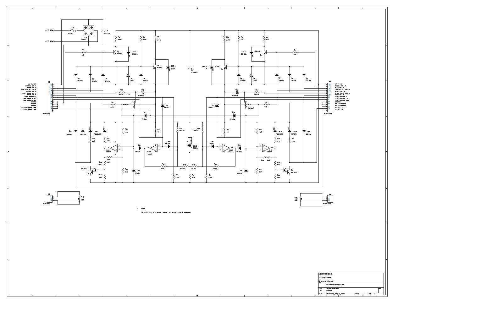
You can check Crest Audio for grounded collector topology. PRO6001/7001 output stage:
Sajti
I think the Crest you want is the Pro9200, which is the biggest class H they made. It has common emitter outputs with output taken off the collector, similar to QSC’s PLX series. The output stage is sort of a CFP-with-gain, sort of like that old and very hated Universal Tiger. Modern output devices and decent simulation tools were needed to make it work. Those amps didn’t use the QSC modified transnova circuit because they use switch mode supplies, and have to feed both channels from it. Two independent supplies would be cost prohibitive.
The old QSCs required independent supplies, but were simple and bulletproof. The old Crests were more like a classical Lin topology. But what do they all have in common? They are all pretty easily converted to a class H simply by adding rail switches, which is pretty much all the bigger ones did. Most amplifiers do lend themselves to doing this, and you don’t need to be at the kilowatt level to take advantage.
The old QSCs required independent supplies, but were simple and bulletproof. The old Crests were more like a classical Lin topology. But what do they all have in common? They are all pretty easily converted to a class H simply by adding rail switches, which is pretty much all the bigger ones did. Most amplifiers do lend themselves to doing this, and you don’t need to be at the kilowatt level to take advantage.
Thanks for all the help.
Something NEW will happen on my next few posts. A statement on the current Class G/H state of the art along with critique of the drawbacks for each approach. Not general principle of the classes , but current circuits in real amps.
I had learn a lot about this tech to reach a superior level. The result is a output stage that is indistinguishable from a standard EF3 except for it's enhanced efficiency. A very strange side effect is observed in my circuit. higher load or higher level results in lower THD well into the class G region. I added two internal feedback loops that are new and stabilized the tracking reference impedance with a current source. Within this stage even the low voltage rail diode switching is minimized actively by feedback.
That's all crest had to do to make their units possibly outperform a 3K$ "audiophile" unit. Project level will be in line with a standard EF3. (Simple !!).
OS
You can check Crest Audio for grounded collector topology. PRO6001/7001 output stage:
Sorry, wrong picture was inserted. This is the right one:
Attachments
Still the same as the smaller Crest. Neither Schottkey or stepper device switching is addressed (properly).
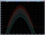
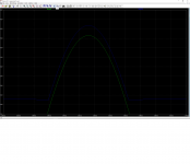
I see the local feedback from the zener/stepper reference back to the driver stage. The capacitive shunting I see basically restricts the stepper bandwidth to assure stability. (below) is fast,stable, non-switching operation. Outer devices minimum current never drops below 12ma , no diode/ device current or voltage "glitches" that can be seen. I have not posted the circuit which produced that simulation yet. It will be included with my "critique " so I might get some feedback from the forum on anything I might have missed. "the circuit" uses local transitional compensation and controlled impedance but is nearly as simple as the Crest solution.
PS - simulating an original crest schematic does not produce results that are as graceful on high freq. square waves or extra switching distortions. The class H "audiophile" designs get to this point with a lot more circuitry.
OS
Attachments
Pete,
Your adventure into this class of output stage intrigues me!
As result I will surely build whatever it is that you are willing to share with us. I am certain many here agree with me.
Your adventure into this class of output stage intrigues me!
As result I will surely build whatever it is that you are willing to share with us. I am certain many here agree with me.
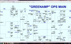
I have the flu now , so it is taking longer to write and edit my longer "critque". [below] is the whole Greenamp class G stepper. I used local AC analysis to set it's bandwidth and phase. When you do the whole output stage analysis , it matches what the core EF3 one does. So , the class B stages are transparent. A trick for monitoring diode switching garbage is to see it at the VAS. NFB highlights the AB switching especially. Without the feedback(s) or the non-switching bias , you will (distinctly) see 6 pulses per cycle.
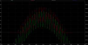
OK , I feel so sick .... Below is the whole shabang. I can swap any models , It still works flawlessly. The design must be what is "holding together". The 3,000$ audiophile Class H designs actually use computer controlled MOSFET stepping with predictive capabilities to do basically what my simple design does. Below ASC is set at two freq. carrier simulation. Feel free to throw ` square waves at it. Or ask questions.
OS
Attachments
Nice solution for the output stage, I would say masterpiece!
The only problem I see, that 2SC5171/2SA1930 is no longer available. So it will be hard to build without them.
Maybe we can try to optimize for some other popular, but available driver?
Sajti
Ps: I hope You get well soon!
The only problem I see, that 2SC5171/2SA1930 is no longer available. So it will be hard to build without them.
Maybe we can try to optimize for some other popular, but available driver?
Sajti
Ps: I hope You get well soon!
Nice solution for the output stage, I would say masterpiece! The only problem I see, that 2SC5171/2SA1930 is no longer available. So it will be hard to build without them. Maybe we can try to optimize for some other popular, but available driver?
Sajti
Ps: I hope You get well soon!
I hope so , this one I had to use mental LT to reach the answer. Read a lot of papers/patents ,too. There is one issue at 2R , CFP driver impedence is too high to drive 20A outer device stepping. This is unrealistic , and might never happen in a real amp. R117=68R + R121= 4.7k would fix this. I will hunt for drivers.
OS
Simulation works quite well with MJE15032/33 too.
Sajti
Slower , will trianglulate 250khz squarewaves. Overkill 😀😀.
I will hunt for drivers.
OS
That will be hard to find. The only possible drivers I can immagine:
2SC4793/2SA1837 Unisonic from Profusionplc
2SC4883/2SA1859 Sanken from Digikey
Every other TO220 is slow.
TO-126 versions are not rugged enough...
Maybe TTC004B/TTA004B?
Sajti
I would imagine you considered using a MOSFET as the switching element? This example does switch off, but it seems to perform well (I have been playing with component values, the image posted is not fully optimized).
Attachments
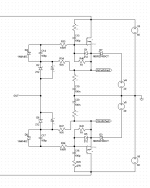
I would imagine you considered using a MOSFET as the switching element? This example does switch off, but it seems to perform well (I have been playing with component values, the image posted is not fully optimized).
A lateral version would be awesome.
I stated that would be next.
OS
That will be hard to find. The only possible drivers I can immagine:
2SC4793/2SA1837 Unisonic from Profusionplc 2SC4883/2SA1859 Sanken from Digikey Every other TO220 is slow. TO-126 versions are not rugged enough... Maybe TTC004B/TTA004B?
Sajti
Think outside the box ...
The main stepper transistor needs to be high Vceo , derating this in SOA between the inner and outer pairs is how class G can get 2X the power. The stepper drivers could even be 80 Vceo , as long as they are fast.
Those 2sc4883A/sa1859A are very good !!! Use them for both the inner EF3 and the steppers. http://www.semicon.sanken-ele.co.jp/sk_content/2sc4883_ds_en.pdf Go all the way and use all sanken - 2SC3264 /SA1295
http://www.farnell.com/datasheets/1854823.pdf SOA at half high rail is 10A+ . Greenamp would be 300 watts. The sankens have much less beta droop when used as outputs , ring emitter mt-200's .
OS
A friend of a friend asked me if I could look into his non functional (simex sph-150 class H).
Very non repair friendly, 2 blown irf740 from power supply + a elec. Capactor.
No ic just a small double-sided size of very small as a. poststamp. No schematics. One of those fun, fun, fun so long it lasts.
Very non repair friendly, 2 blown irf740 from power supply + a elec. Capactor.
No ic just a small double-sided size of very small as a. poststamp. No schematics. One of those fun, fun, fun so long it lasts.
Those 2sc4883A/sa1859A are very good !!!
OS
My favourite drivers! Best combination with the Sanken output devices.
Sajti
My favourite drivers! Best combination with the Sanken output devices.
Sajti
If these were used a small re-tuning of the C111/112 values would be needed. The Ct of the diode and Ccb of the driver determine these. This is why this design can track a signal so accurately. Impedance control with the simple current sources keeps this "tuning" independent of amplitude (or load).
The original Crest design had these weaknesses.
OS
- Status
- Not open for further replies.
- Home
- Amplifiers
- Solid State
- GreenAmp ++ modulated Class G output