Hmmm. 50A trenchfet - SOA (below)...
That is indeed Hmmm, the Vishay SOA doesn't look like the TrenchFET SOA from IXYS, for instance.
Nor is it consistent with articles like this Are Trench FETs Too Fragile for Linear Applications? | Power Electronics
or this [Resolved] Hotswap FET selection based on SOA with paralleled trench FETs - Power management forum - Power management - TI E2E Community
The first article is oldish so perhaps trenchFETs have improved their linear SOA, IXYS is behind the times and I am mistaken, in which case thanks for the update.
But the second article is reasonably current so perhaps the Vishay datasheet is a bit optimistic.
I still think your particular example is optimistic but won't quibble until I have better data.
Will reply to other stuff later.
Best wishes
David
I built some switched rail amplifiers, about 10-15 years ago. It was almost impossible to remove the switching glitch from the output signal. So this amplifiers are good for subwoofer application, but not for quality music reproduction.
I used +/-110/55V rails, and single IRF2807 for each rail switching. It was realy "dirty" switching, because I optimized for the minimum loss, so the speed was as fast as possible, using LM311 comparators with positive feedback, and push-pull drivers for the MOSFETs.
Sajti
I used +/-110/55V rails, and single IRF2807 for each rail switching. It was realy "dirty" switching, because I optimized for the minimum loss, so the speed was as fast as possible, using LM311 comparators with positive feedback, and push-pull drivers for the MOSFETs.
Sajti
Using the IXYS mosfets for my SA2017 I have destroyed 2 of them very quickly because of bad cooling. Never had problems with other FETs or BJTs in output stage during development. For me it looks like the described trench fet hotspot problem gets very fast worse above 75 degree junction temperature even for the so called "extended FBSOA" parts....
The first article is oldish so perhaps trenchFETs have improved their linear SOA, IXYS is behind the times and I am mistaken, in which case thanks for the update.
But the second article is reasonably current so perhaps the Vishay datasheet is a bit optimistic.
...
OS: Have a look at the vishay datasheet for thermal impedance during switched vs DC operation. The thermal impedance quickly increases to 0.9K/W
BR, Toni
BTW: have you read this post - the lateral mosfet amplifier has very low distortion even with very low bias:2stageEF high performance class AB power amp / 200W8R / 400W4R
BR, Toni
BR, Toni
Cascoded VAS >2V + EF3 >2V + Rail tracker @ 2V + even the cap multiplier @ 1.5V = >7V loss. Yes , to reduce it - no cascode or class H + EF2 and no multiplier. "Burn it" ?? , we just don't use it...
Well, we do "Burn it" because every ampere that we pull from the outer rails produces 10 W of heat across that 10 V drop. For my 600 W into 4 ohm example there's about 18 amps peak = 180 W peak just from that. So, nice to reduce it. I have the cascode on the IPS, as in Damir's amp, that saves a few volts and the loop gain is practically identical above a few kHz. I have VFA sims of EF2 OPS with 20 kHz THD of a few PPM so that is an option I will try. Use both should cut the overhead by a third or so. "Better than a poke in the eye" is the Australian idiom.
Then we need to make sure the rail tracker isn't the choke point once we save a few volts in the earlier circuit. It was the rail tracker I had in mind when I wrote the earlier comment but your reply has made me realize we need to keep both sets of overheads in correct relation, very helpful.
I built some switched rail amplifiers... It was realy "dirty" switching, because I optimized for the minimum loss, so the speed was as fast as possible...
Yes, definite trade off between losses and "dirt". My speakers are efficient so I am prepared to accept the increased losses from linear power rail modulation in return for clean power. I wonder if I can use the outer VFET capacitance to actually smooth the process, haven't worked out if that even makes sense yet.
...mosfets for my SA2017 I have destroyed 2 of them very quickly...
I remembered that, part of the reason I am cautious.
Best wishes
David
Last edited:
Hi Pete,
Here are the models of IXIS devices I used. They seem to work well as what I and Jeff saw in the prototype match my simulations well. Hope they may be of use for you and others here at least for some test simulations 😉
Do you have have a p-channel ?
OS
Do you have have a p-channel ?
OS
Is this what you're looking for?
.SUBCKT IXTK120P20T G D S
** Model generated on September 19, 2012
R_ds D 9 0.02
R_gs G 70 0.001
L_s SG S 1n
R_S S11 SG 0.0001
M111 9 70 S11 S11 MM111 L=1u W=50u
.MODEL MM111 PMOS LEVEL=1
+IS=1e-32
+VTO=-3.7
+LAMBDA=3.88605e-03
+KP=1.00
E_vth 70 71 value={-0.7}
M112 9 71 S11 S11 MM111 L=1u W=90u
E_cdg 70 7dg G S 1
D_c D 7dg Ddg
.MODEL Ddg D
+ CJO=3.3839E-9
+ M=.43387
+ VJ=3.3905
+ N=10
C_vgs1 70 S 44n
#1....Then we need to make sure the rail tracker isn't the choke point once we save a few volts in the earlier circuit. It was the rail tracker I had in mind when I wrote the earlier comment but your reply has made me realize we need to keep both sets of overheads in correct relation, very helpful.
#2 ... Yes, definite trade off between losses and "dirt". My speakers are efficient so I am prepared to accept the increased losses from linear power rail modulation in return for clean power. I wonder if I can use the outer VFET capacitance to actually smooth the process, haven't worked out if that even makes sense yet. Best wishes David
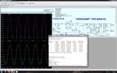
#1 - I just did the simulations on the MOSFET's. They work great for the typical "switched" modulated class G. Very hard to get them in a idle state(for H). I expected this , they do not work as well as a BJT in the linear region. The modeled gate capacitance does have a "lag" effect on the modulation vs. frequency.
With the BJT variant , easy idle ...and you can control the capacitive "lag" up over 10Khz.
#2. - How much power do you really need ? With that efficiency the 8 device (below) would blow you out the window. The X2 is the same as the Crest (cc1800) @ 400W/8R. But .. at 8ppm-10Khz , it scales nice. .ASC is set to idle the modulator devices at 15mA -run 150V p-p @ 10K.
OS
Yup. Added to the collection.Is this what you're looking for?
I was thinking , 8 TO-3p devices are cheaper than the FET's. Mouser has the 2SC5342/2SA1952 for $2.31-2.60 USD. Thanks.
OS
I am prepared to accept the increased losses from linear power rail modulation in return for clean power.
Best wishes David
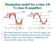
When you just break the class G switching barrier , You have the full voltage of the upper rail switched on even as it is un-needed (by the inner pairs). Class H only applies an extra 4-6V over what the signal requires. Which scenario would be more efficient ? The upper device is always at some level of Vce instead of being fully "turned on". You would think these factors would negate each other. Actually , the reduced loss from the inner pairs more than negates the outer pair's increased losses.
Nope , from ADSL drivers to audio .... class H is 5-10% more efficient overall than the "dirty switcher" (class G). Most of this efficiency is shifted right to the transition between AB and H operation.(below 2). The dirty class G gets it's peak before transition. It also seems class H gets just a little more efficiency all the way to full power. This information seems to be consistent across the internet , once you go beyond the dummies that do not even know the difference between G/H.😀
Attachments

- How much power do you really need ?
Maybe not "need"😉 But my baseline is 600 W @ 4 ohms to drive JBL-pro 15" woofers (2226) to their nominal limit. That should also be suitable for the 18" subs (2245"). Also a 150 W @ 8 ohm mid amp. (My class B+ had an OPS where each increment was 100 W so I had planned 200 W for the nominally 150 W driver, realistically 100 W would be plenty.) Plus amps for the tweeters, hardly need class H for that.
Nope , from ADSL drivers to audio .... class H is 5-10% more efficient...
In simple theory they should be the same, probably depends a little on the details in practice. In any case, I was a bit careless in what I wrote, just meant that I was prepared to take some penalty on efficiency to have less "dirt" on the rails. Didn't mean to imply switchers were necessarily more efficient. I did consider a switched buck down-converter, which really would be more efficient. Now I come to think it over, the fact that they aren't (in this case) means less to worry about and makes the choice simple.
Best wishes David
Then we need to make sure the rail tracker isn't the choke point once we save a few volts in the earlier circuit..we need to keep both sets of overheads in correct relation...
Now I think some more and see the rail tracker should waste minimum volts because this means we can keep more Vce across the inner transistors near the peaks. That helps keep their Ft up and improves stability. That makes the common source (or BJT CE) rail tracker still look like the choice.
David
Has anyone actually evaluated the transistors from Unisonic?
Transistors from Unisonic | Profusion
I think we should avoid paranoia and find out if their transistors are okay. ASTX tried the 4793/1837 on the curve tracer compared with the original Toshibas and the DC characteristics looked fine.
I now count 4 different datasheets for the 2SC5200/A1943, from Toshiba, Fairchild, Onsemi, and Unisonic.
Sims with the IXYS VFETs as the outer transistor are beautifully clean, no transition spikes or twitches at all. Unfortunately the VTO is 4 volts so we lose a bit more overhead than a BJT. It's not easy to use Common Source and pull the FET "down", as I learned when I tried. I want the VFET benefits but want to avoid excessive losses. Winfield Hill had the clever idea to create boosted rails with a tiny, isolated DC-DC power supply. Seems to me it would be possible to do a similar trick here, rather than boost the rails just boost the Gate of the FET. Kind of a linear hi-side driver. The power is tiny so even the smallest part should work, there are some on D.key for less than $2. Any noise should be outside the audio band and can be well filtered, plus it's in the OPS, not the sensitive input. Has anyone seen this done or have ideas?
Missed the edit window. It now occurs to me that photovoltaic couplers would work well for this. Quieter, smaller, even less expensive, nicer somehow. Can perhaps power them off bias current we need anyway, so they use effectively zero power.
David
Missed the edit window. It now occurs to me that photovoltaic couplers would work well for this. Quieter, smaller, even less expensive, nicer somehow. Can perhaps power them off bias current we need anyway, so they use effectively zero power.
David
Hi Dave
I would keep SMPS away from audio circuits. Their noise is NOT just high-frequency. Much easier to stay within linear means for this, like a simple charge pump.
There is certainly an advantage to be able to use all n-channel tier switches but the driver complications rise up... There do not seem to be any real complementary mosfets with low Rds-on, so losses are always asymmetric as is clipping.
In most cases, you get the best linear performance by accepting some waste heat. For example, THD is doubled just by going from 15V zeners to 12V in the "look ahead" supplies used to switch mosfet rail switchers.
I would keep SMPS away from audio circuits...
Yes I am wary, but SMPS can be very clean if they are carefully done, the famous Halcro amp for example.
Better documented on DIYaudio is Jens' RTX audio analyser, he eventually found it easier to shield the noise of an SMPS rather than the low frequency magnetic field disturbance of a mains transformer.
But it's a bit moot because I have played around with this since I last posted - and decided to skip "clever" tricks, use a simple boosted VAS rail tapped from the main transformer.
...the driver complications rise up... There do not seem to be any real complementary mosfets with low Rds-on, so losses are always asymmetric...
IXYS has Mosfets with low Rds-on and acceptable SOA in both N and P.
They could be closer to complementary and there will be some inevitable asymmetry but I think they will be acceptable.
It seems preferable to a circuit with the driver complications you mention.
accept... some waste heat. For example, THD is doubled just by...
Yes, this is the part of the work I need to do next, determine the best heat versus THD trade-off for my circuit.
Winter here soon, spend some time with LTspice after dark when it's cold.
Last edited:
Hi Dave
Radiated noise from SMPS is not the issue; rather, it is the conducted noise that gets into every trace. I found it too much to deal with, although part of my problem was that the SMPS was on the main board and board revisions were expensive. A friend using SMPS went through many tribulations but at least he had a separate PSU card fo his project.
IXYS has a lot of nice products - some of them theoretical - and most more expensive than the usual offerings. I'm not crazy about single-sourced parts. Their line of linear-rated mosfets is neat and the P-ch are inherently linear-rated because of their fabrication process.
Radiated noise from SMPS is not the issue...
Yes, I meant that Jens found that he could obtain lower overall noise from the SMPS compared to the small mains transformer, despite the problem of conducted noise from the SMPS.
IXYS has a lot of nice products...most more expensive than the usual...Their line of linear-rated mosfets is neat and the P-ch are inherently linear-rated because of their fabrication process.
There seems to be be no competitor for some of their products so not really "more" expensive.
Like you, I would prefer not to be locked to one vendor but IXYS make parts that fit my requirements, more or less.
What other 100 - 200 V, < 50 m-ohm, linear rated Mosfets are there?
Best wishes
David
- Status
- Not open for further replies.
- Home
- Amplifiers
- Solid State
- GreenAmp ++ modulated Class G output