Sorry if I was too heavy handed in my criticism of the BC550/560, I had the start of a cold and was a bit unsettled.
Don't warry, I don't produce those transistors.😀
And what do You think about the 2SC2240/2SA970? They were very popular in many amplifiers...
Yes, I know they are popular but I have never used them myself, and Art of Electronics doesn't have any data for them.
Now that they are hard to find, it doesn't seem worthwhile to invest a lot of time in study of the datasheet, but Toshiba was reputable and I assume they were popular for a reason.
So they are/were probably pretty decent.
Best wishes
David
Now that they are hard to find, it doesn't seem worthwhile to invest a lot of time in study of the datasheet, but Toshiba was reputable and I assume they were popular for a reason.
So they are/were probably pretty decent.
You can find the smd version of them: 2SC3324/2SA1312. So it looks worth to give them a try...
Sajti
You can find the smd version of them: 2SC3324/2SA1312...
My mistake, I even made a note of that because AoE doesn't mention the equivalence (normally they list both numbers) but it slipped my mind.
OK, They are not as quiet as the Zetex but pretty decent Rb ~35 and 20.
Nicely linear, Hfe of >200, low Cob, >120 V breakdown decent Early VAF - all round nice transistor, as expected.
Best wishes
David
Now we are done with noise, back to the OPS!
That's not a concession, that's a win.
Now you have a better circuit without the problems of the super pair.
Before you layout I have a few more proposals.
I have only used BJT OPS but I think IXYS VFET transistors would work really well here, robust and powerful.
Quick estimate is that my planned 600 W would only need one inner and outer transistor per polarity.
That could be an exceptionally compact amp for the power.
In any case, the idea of VFETs has had an excellent side effect - made me think about the volts dropped across the outer transistors.
I think VFET outer transistors could be connected as common source to reduce the losses without the need for even more rails for a boosted VAS.
Have you considered this?
I started a discussion about a rail-to-rail audio amp (common source OPS) a while back but it never went far, the bias circuitry is OK for IC manufacturers but becomes problematic for DIY.
Common source would be fine for the outer transistors because there isn't the same need for precise bias.
Best wishes
David
I concede , the super-pair is beat by the Hawksford.
That's not a concession, that's a win.
Now you have a better circuit without the problems of the super pair.
... Wait till you see this...layout.
Before you layout I have a few more proposals.
I have only used BJT OPS but I think IXYS VFET transistors would work really well here, robust and powerful.
Quick estimate is that my planned 600 W would only need one inner and outer transistor per polarity.
That could be an exceptionally compact amp for the power.
In any case, the idea of VFETs has had an excellent side effect - made me think about the volts dropped across the outer transistors.
I think VFET outer transistors could be connected as common source to reduce the losses without the need for even more rails for a boosted VAS.
Have you considered this?
I started a discussion about a rail-to-rail audio amp (common source OPS) a while back but it never went far, the bias circuitry is OK for IC manufacturers but becomes problematic for DIY.
Common source would be fine for the outer transistors because there isn't the same need for precise bias.
Best wishes
David
Last edited:
I think VFET outer transistors could be connected as common source to reduce the losses without the need for even more rails for a boosted VAS.
Have you considered this?
Like this?
Attachments
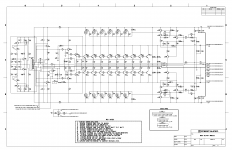
Like this?
That is a little hard to read but it looks very similar to what I had in mind, thanks!
Is there a better copy or a circuit explanation, service manual maybe?
Best wishes
David
I found some information.
Last edited:
That is a little hard to read but it looks very similar to what I had in mind, thanks!
Is there a better copy or a circuit explanation, service manual maybe?
Best wishes
David
I found some information.
It is a bit overkill for home....
Service manual:CRESTAUDIO PRO 10001 Service Manual download, schematics, eeprom, repair info for electronics experts
Sajti
It is a bit overkill for home....
Of course, I don't plan to build one!
But it is nice to see they have worked out a similar circuit when faced with professional equipment requirements for efficiency and reliability.
Also makes my estimate of one outer VFET for each rail look plausible for my 600 W woofer amp.
They use one per ~400 W but the amp is 20 years old and VFETs have improved.
So the whole idea continues to look pretty nice - reasonably efficient and compact, very low noise, and I believe I can keep it fairly simple and the distortion very low.
Best wishes
David
Thanks for the manual link
Last edited:
Like this?
That is a dirty switcher. 😛
The only "audiophile" variant of that type design is by Emotiva . They basically
have a microprocessor running the mosfet's.
Processor actually takes the music into account and 'softens" the switching.
They get .001% thd , but with a lot of complication.
OS
That is a dirty switcher. 😛
Driving 10kW subwoofer? It can be dirty 😀
Sajti
That is a dirty switcher...
Why dirtier than your circuit?
Apart from the fact it's a 4.4 kW Public Address amp and not optimised for lowest distortion.
Best wishes
David
The BC817/807 are SMD equivalents for the TO92 BC327/337, of which the -40 grades can still be bought on Mouser.
"Dirty" is relative . ALL class G/H OPS's are dirty , but some are dirtier. If you ask , my outer pairs do not turn off. But I still have the Schottky's. Dirty is more efficient , outer pairs are hard OFF short of class G/H operation. OEM Class G typically goes hard off , as well. But since it just toggles between 2 states , it can be less efficient.
Emotiva does this for class G , their mosfet's idle between switching and will switch according to input requirements. Looking at some IP schema's I have , I think they feedback the diode "glitches' with some advanced error correction. The end result is the same 20-30PPM / 10Khz that I get the analog way.
PS - In a Emotiva amplifier review , the reviewer could actually hear the 10K switching at full power. At 20K , the amp went into protect mode. Normal musical input was effortless.
OS
With VFETs as the outer transistors there are no minority carriers to soak up - so I don't see a need to keep them on, should be more efficient and still clean.If you ask , my outer pairs do not turn off...
Best wishes
David
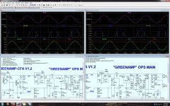
Unless the Exicon models are wrong , I get similar results. The outer pair pre-driver sees the same 500-700pF capacitance with either BJT/mosfet. Are the Exicons Vfets ? What also works well are the cheap "trenchfets" (D-pac/to-220). You only need about a 50W device , the class H outer pair devices will just have 10-30V to deal with. Again , the Emotiva uses just 3 TO-220 high current low Rdson MOSFET's as the outer pair (in parallel). (below) are the FET/BJT simulations.
OS
OS
Attachments
Are the Exicons Vfets ?'''
No.
What also works well are the cheap "trenchfets" (D-pac/to-220). You only need about a 50W device , the class H outer pair devices will just have 10-30V to deal with.
Trench FETs are excellent for a switched rail scheme, I very much doubt they are suited to a Class H amp where the rails track linearly, the SOA is poor. I don't see how a 50 W device will survive at elevated power levels, my baseline is that the outer devices have 55 V = 20 V inner and 75 V outer.
...the Emotiva uses just 3 TO-220...(in parallel).
I am unfamiliar with the circuit of the Emotiva, it sounds more complex than I want so I haven't spent the time to look at it - do you have a quick link so I can see how relevant?
(below) are the FET/BJT simulations.
Thanks for that but I can't run the FET sim because you didn't attach the FET models. And of course I can't see if those models are OK. From your picture it looks like the FET simply replaced the BJT, not adjust for different bias and turn on, maybe not optimal? When I did a BJT sim (on an old version) I notice the amp clipped at about 50 V peak output with 60 V rails 10 V seems a lot to burn, I think it can be reduced, have you looked at this?
Best wishes
David
Last edited:
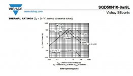
Hmmm. 50A trenchfet - SOA (below).
Between the 30V and 60-70V rails is 30-40V. As you transition into H , you start at 30V (Vds) , quickly race towards the high rail. Vds is < 20V for most of the 15mS on a 20Hz waveform. Plenty of SOA @ <20V + <10mS. We are only dealing with 1/4 of the rail to rail potential on each partial cycle of even the slowest waveform.
Emotive "gen-3" - XPA-5 Gen3 – Emotiva Audio Corporation
I violated IP to get the schematic - won't post it. BTW , look at the AB module .... just 2 low Rdson FET's - for 3 pair TO-3p BJT. You can also see the 2 D-PAC schottky's right above the "switchers". Actually , this amp is a CPU controlled G and H.
Attachments
When I did a BJT sim (on an old version) I notice the amp clipped at about 50 V peak output with 60 V rails
10 V seems a lot to burn, I think it can be reduced, have you looked at this?
Cascoded VAS >2V + EF3 >2V + Rail tracker @ 2V + even the cap multiplier
@ 1.5V = >7V loss.
Yes , to reduce it - no cascode or class H + EF2 and no multiplier.
"Burn it" ?? , we just don't use it. Or boosted rails ,, but that would be a partial fix. Just get a 70-75V high supply - far easier.
OS
TrenchFETs from IXIS
Hi Pete,
Here are the models of IXIS devices I used. They seem to work well as what I and Jeff saw in the prototype match my simulations well. Hope they may be of use for you and others here at least for some test simulations 😉
.MODEL IXTK120N25 NMOS
+ LEVEL=3
+ L=2.0000E-6
+ W=740
+ KP=1.0401E-6
+ RS=10.000E-3
+ RD=5.4362E-3
+ VTO=3.7831
+ RDS=5.0000E6
+ TOX=2.0000E-6
+ CGSO=13.514E-18
+ CGDO=1.9406E-12
+ CBD=7.2767E-9
+ MJ=1.5000
+ PB=3
+ RG=10.000E-3
+ IS=53.461E-6
+ N=5
+ RB=1.0000E-9
+ GAMMA=0
+ KAPPA=0
.SUBCKT IXTK120P20T G D S
** Model generated on September 19, 2012
R_ds D 9 0.02
R_gs G 70 0.001
L_s SG S 1n
R_S S11 SG 0.0001
M111 9 70 S11 S11 MM111 L=1u W=50u
.MODEL MM111 PMOS LEVEL=1
+IS=1e-32
+VTO=-3.7
+LAMBDA=3.88605e-03
+KP=1.00
E_vth 70 71 value={-0.7}
M112 9 71 S11 S11 MM111 L=1u W=90u
E_cdg 70 7dg G S 1
D_c D 7dg Ddg
.MODEL Ddg D
+ CJO=3.3839E-9
+ M=.43387
+ VJ=3.3905
+ N=10
C_vgs1 70 S 44n
*
*
L_sd subd S 1n
D_1 D subd BD1
.MODEL BD1 D
+ IS=53.975E-15
+ N=.8356
+ RS=1.7992E-3
+ IKF=23.171
+ CJO=22.563E-9
+ M=.53013
+ VJ=.3905
+ ISR=73.153E-9
+ BV=199.90
+ IBV=25.911E-3
+ TT=122.57E-9
.ENDS
Cheers,
Valery
- Status
- Not open for further replies.
- Home
- Amplifiers
- Solid State
- GreenAmp ++ modulated Class G output