How about horizontal, +/- 15 degree? Should be OK, right?
Is it better than the (shaded) array? Or just different...
Is it better than the (shaded) array? Or just different...
I see what you mean, it does give the impression of something more like the Beolab 90. In the directivity plots the nulls can be moved around, screenshot attached for anyone who hasn't seen it.what claims? "steerable acoustic directivity" seems exaggerated
I like the idea enough to build it with the drivers I already have so a simulation will be the next step. A big round horn with a HF1440 on top of a cardioid woofer box seems like a reasonable idea 🙂If it does act like the VituixCAD prediction it would work quite well with a horn reaching low enough. (be it a horn with rim drivers or Synergy or just a big (two way?) compression driver)
Its not as good as the 20H, 15V listening window curve in the previous posts would have you believe. These have axial and in-room overlays for 0, 5, 10, 15 degrees reference angle:
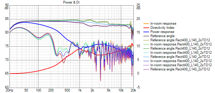
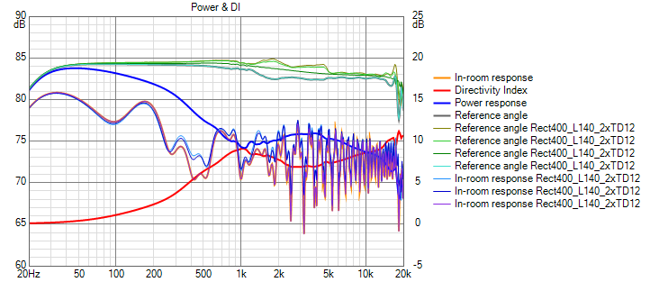
The arrays seem better below 5 khz over the same H window, if I model with 20 db wall absorption. Without the wall absorption, large boundary nulls appear. Above 5 khz the narrowing H window of the array is apparent.

The arrays seem better below 5 khz over the same H window, if I model with 20 db wall absorption. Without the wall absorption, large boundary nulls appear. Above 5 khz the narrowing H window of the array is apparent.
Attachments


I see what you mean, it does give the impression of something more like the Beolab 90. In the directivity plots the nulls can be moved around, screenshot attached for anyone who hasn't seen it.
I like the idea enough to build it with the drivers I already have so a simulation will be the next step. A big round horn with a HF1440 on top of a cardioid woofer box seems like a reasonable idea 🙂
I would agree with that. Very little wrong with such a system and what there is probably could be fixed by making the horn even bigger. Have you looked at how the reported directivity extension of a mouth roll back compares to that of a rim array?
I've looked at the difference in separate graphs but not compared them directly.Have you looked at how the reported directivity extension of a mouth roll back compares to that of a rim array?
The rolled back guide doesn't necessarily control the directivity as low as a similar size guide in a baffle and enclosure can if the enclosure is the right size and shape. It lets go very smoothly though. The four driver slot ring simulation I did could extend the directivity lower than the guide alone but whether the extra complexity would be worth it when used with a cardioid woofer tower is less clear. I'll have to get back into the simulations at some point to see.
This time it is attachedIn the directivity plots the nulls can be moved around, screenshot attached for anyone who hasn't seen it.
Attachments

There is some more information and a look at the GLM software and some results as part of webinar on the W371A. The link is to a recording no need to register.
https://register.gotowebinar.com/recording/viewRecording/8449341546397558032/1033099333340805644/ilkka.rissanen@genelec.com?registrantKey=8039400730648966160&type=ATTENDEEEMAILRECORDINGLINK
There is the usual preamble and selling related positivity but it was interesting
https://register.gotowebinar.com/recording/viewRecording/8449341546397558032/1033099333340805644/ilkka.rissanen@genelec.com?registrantKey=8039400730648966160&type=ATTENDEEEMAILRECORDINGLINK
There is the usual preamble and selling related positivity but it was interesting
Something else I came across today, a chat with Floyd Toole A chat with Dr. Floyd Toole | Audio Science Review (ASR) Forum
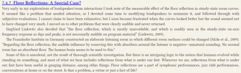
At about 1 hour 20 minutes there is a discussion of vertical reflections with mention of a section of Floyd's book which I attached below. Seems relevant to the discussion, also reminded me of resonances in speakers being a real issue which is why I think that introducing Directivity lumps and bumps is not a great idea.
At about 1 hour 20 minutes there is a discussion of vertical reflections with mention of a section of Floyd's book which I attached below. Seems relevant to the discussion, also reminded me of resonances in speakers being a real issue which is why I think that introducing Directivity lumps and bumps is not a great idea.
Attachments
I've got a few personal views on that matter, as I've experienced both in my room.
It is obvious why such a floor reflection wouldn't be particular bothersome. We are used to hearing rooms, especially rooms that we spend more time in.
It gives us information about the space, and that info is validated by our eyes. We don't think about it, but have learned to do it on auto-pilot.
As I want to maximize the effect the recorded queues have (if they are present). Meaning: if there is a hint of space in the recording, I want to experience that space as much as possible. The "being there" concept. Why would I accept adding a floor bounce, that simply projects "my space" over the recorded environment? For the same reasons I remove early reflections. This is my personal preference however. If I were to build a background system, I wouldn't think twice about floor bounce or phase. But to maximize listening pleasure, I'm willing to go that extra mile. To each his/her own. 😉
I do agree with lumps and bumps in the DI not being a bright idea. It will make it quite a bit harder to find an acceptable/pleasant room curve.
The room response will be less predictable and most probably will offset tonality from recording to recording.
But looking at DI alone isn't everything. You've got to see what you have within your space and (if possible) adjust that. DI is a wonderful tool for a speaker maker, as it would/should work in most rooms, however one cannot simply assume every room boundary to reflect that beautiful DI as 'even' as would be the ideal goal. Adjusting the room to what you have in the area of interest might be another way to deal with a (slightly?) less than ideal DI. Who has a listening space that is as nice and even as the ones at Harmon anyway. Not me! But the concept is valid. In practice we may have to adjust what works to our own environment. Starting with a smooth DI curve would make that part way easier.
As I see it, the suggested simulations with the horn and all the add-ons don't really have the advantage I would look for in a speaker. Which is why I asked how it compared to the array sims. As what I've seen here is we started with a little problem, solved that, and in the proces create an even more imbalanced end result than what we started with.
I've been looking back within this thread, looking for things like the shape of the DI curve. I have to say I've seen some older concepts within this thread that I think were moving in a better direction than the latter suggestions. Those last ones seem overly complex for what it is they are trying to solve. If I'm brutally honest.
I agree with this statement.I have to say I've seen some older concepts within this thread that I think were moving in a better direction than the latter suggestions.
As to the other stuff I'll reserve judgment until I can compare the difference side by side 🙂
All I've been doing for the last several weeks is trying to get rid of the lumps and bumps in the DI and power responses. They seemed small but nothing I tried eliminated them completely. The question in my mind bcame what is good enough?
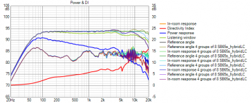
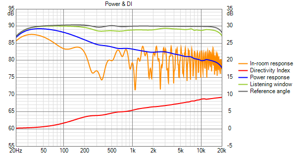
I attempted to answer it by re-looking at a conventional 2-way waveguide speaker to see if it justified all the extra work I was doing. For a W-waveguide-W configuration, 12" woofers at 300mm CTC, I found nothing to complain about except the floor/boundary null.

On my first pass through these sims, my goal was to eliminate that boundary null. I thought it would be easier than it turned out to be. Floyd says quite clearly that its not worth the effort. I wasn't aware of that particular quote but I was aware of the underlying theory/argument as discussed by Wesayso as well as in the quoted text. While I wasn't sure to what extent it was true, I have understood that the primary benefit of line array like vertical directivity may not be listening so much as when taking measurements at the listening position. That is a significant benefit especially if the speaker is large or if doing the kind of DSP processing that W does.
This simulation shows that if you disregard the boundary null(s), (and have a good waveguide) then its not hard to get a smooth DI and power response. With this as a standard of comparison, I can see that nothing I do to ease the room integration should be at the expense of the smoothness of these curves. I've been moving in this direction for some time now. With your two posts, I would say that redirection is complete. Where I will end up, I can't say but I will be steering differently.
I attempted to answer it by re-looking at a conventional 2-way waveguide speaker to see if it justified all the extra work I was doing. For a W-waveguide-W configuration, 12" woofers at 300mm CTC, I found nothing to complain about except the floor/boundary null.
On my first pass through these sims, my goal was to eliminate that boundary null. I thought it would be easier than it turned out to be. Floyd says quite clearly that its not worth the effort. I wasn't aware of that particular quote but I was aware of the underlying theory/argument as discussed by Wesayso as well as in the quoted text. While I wasn't sure to what extent it was true, I have understood that the primary benefit of line array like vertical directivity may not be listening so much as when taking measurements at the listening position. That is a significant benefit especially if the speaker is large or if doing the kind of DSP processing that W does.
This simulation shows that if you disregard the boundary null(s), (and have a good waveguide) then its not hard to get a smooth DI and power response. With this as a standard of comparison, I can see that nothing I do to ease the room integration should be at the expense of the smoothness of these curves. I've been moving in this direction for some time now. With your two posts, I would say that redirection is complete. Where I will end up, I can't say but I will be steering differently.
Attachments
Last edited:
The shape of the DI in general somewhere around 3dB per decade is quite similar to the JBL 4349. While that has some odd crossover choices which make the measurements look ordinary, the subjective review from Amir was quite positive. This post shows a spin with both horizontal and vertical DI as separate traces.
How to make quasi-anechoic speaker measurements/spinoramas with REW and VituixCAD | Page 3 | Audio Science Review (ASR) Forum
How to make quasi-anechoic speaker measurements/spinoramas with REW and VituixCAD | Page 3 | Audio Science Review (ASR) Forum
a quote from that thread:
" I've not seen a constant directivity speaker with perfect verticals"
" I've not seen a constant directivity speaker with perfect verticals"
Add another woofer down low by the floor to help soften the floor bounce dip for critical listening and you're done? 🙂
here is what I get with 3 12s in front
Better? not really and not good enough. That deep narrow null in the original sim is likely less audible than the shallower wide dip.
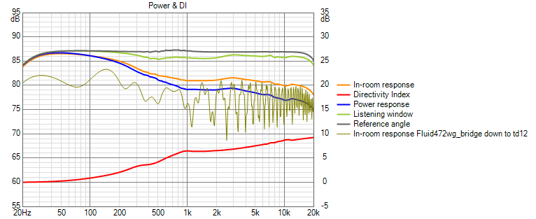
My intention was and is bridge drivers around the waveguide with a big woofer at floor level covering up to where the floor null would otherwise be. The rim slots were supposed to do this but for some reason the rim slots have a rising power response which when joined with the falling power response of the waveguide leaves a hump in the power response, albeit less than 2 db tall
If I change the high pass on the two 12's flanking the waveguide to 400 Hz, I get this which is what it would look like with bridge drivers.
Now the question is what to use for bridge drivers as clearly two husky twelves aren't appropriate; perhaps pairs of 5FE120's, my favorite 5" drivers.
Better? not really and not good enough. That deep narrow null in the original sim is likely less audible than the shallower wide dip.
My intention was and is bridge drivers around the waveguide with a big woofer at floor level covering up to where the floor null would otherwise be. The rim slots were supposed to do this but for some reason the rim slots have a rising power response which when joined with the falling power response of the waveguide leaves a hump in the power response, albeit less than 2 db tall
If I change the high pass on the two 12's flanking the waveguide to 400 Hz, I get this which is what it would look like with bridge drivers.
Now the question is what to use for bridge drivers as clearly two husky twelves aren't appropriate; perhaps pairs of 5FE120's, my favorite 5" drivers.
Attachments


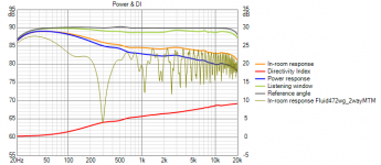
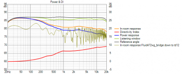
here is what I get using pairs of 5FE120s above and below waveguide at +/-200mm, bridging down to TD12 at -700mm from wg center.
The further up I move the XO to the WG, the better the in-room looks in the 500 Hz to 1 kHz region. I started at 650 Hz and left it at 800 Hz. You can see that the power response and PIR are just starting to develop a hump around 3 khz, like it did with the rim slots. The hump increases its height with XO frequency.
The advantage of the larger axisymmetric WG is that it holds vertical pattern lower than the rectangular, allowing this hump to be largely avoided. The rim slot array isn't able to correct the vertical pattern of the rectangular waveguide all the way up to 3 khz because around 1500 Hz, it develops vertical lobes due to CTC.
Attachments
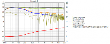
The quad 12" cardioid woofers suggested by Fluid and Kimmo may be just what the doctor ordered used with a waveguide on top
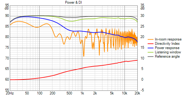
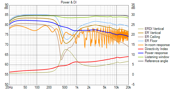
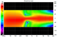
This is my rectangular waveguide with rim slot drivers on top of 2 12" front woofers and two 12" side woofers making for a cardiod response below 500 Hz. The DI has two minor peaks. The one at 300 Hz is associated with a ceiling null. The one near 1 khz is where the rim slots start vertical lobing and cross to the waveguide.
I was impressed to see Kii Audio doing likely better with a small tweeter waveguide and cardioid midrange in a turn key solution.
Kii Audio ::: kii_three
Attachments

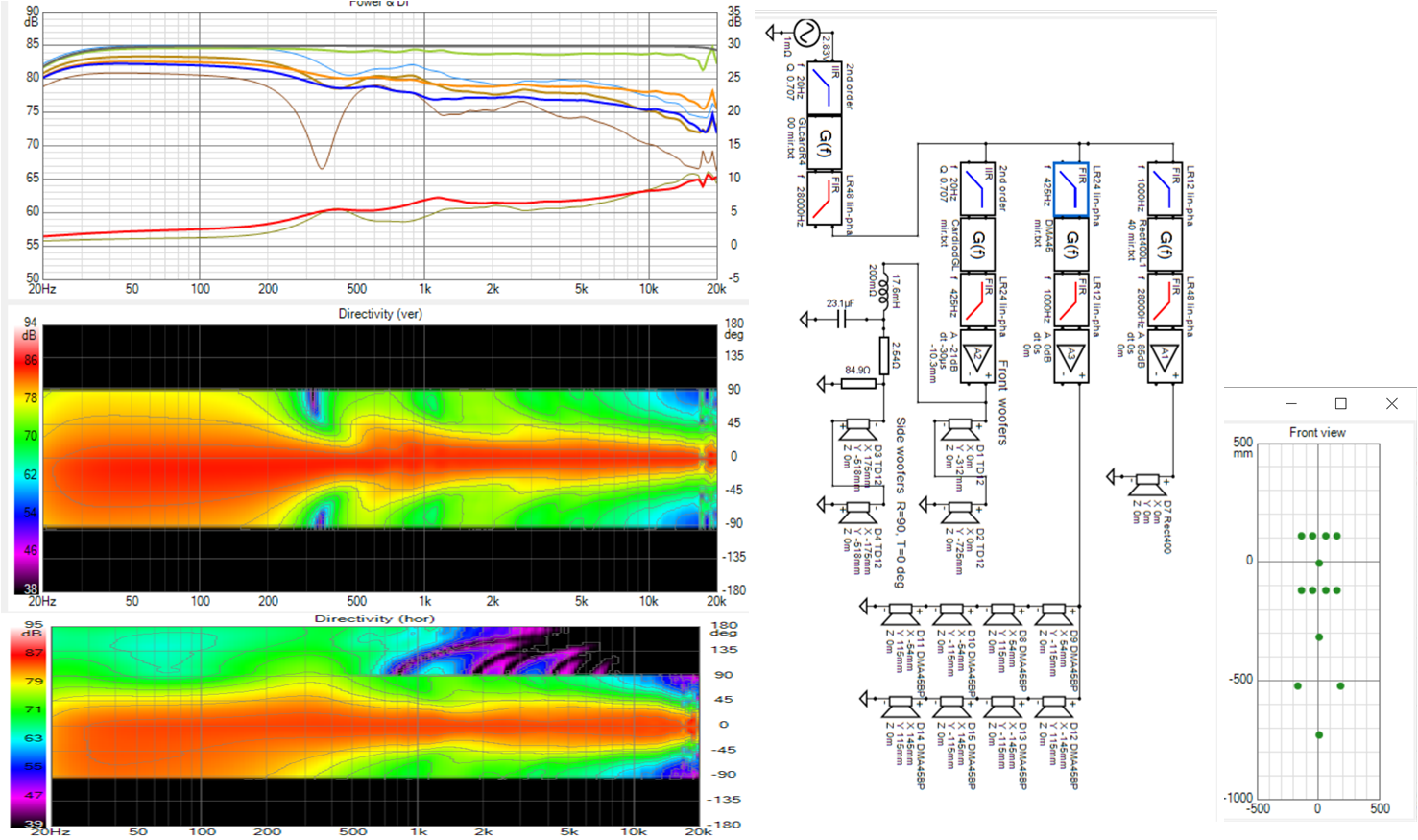
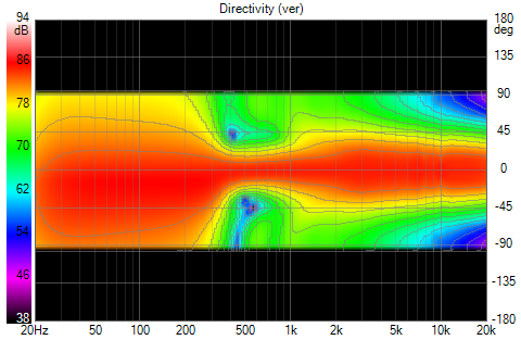
I get a similar but nicer simulated response with Fluid's larger, 472mm dia. HF1440 waveguide and rim slots. The larger waveguide makes for a smoother transition to the woofers evident in the vertical polar map.
I've always like cardioid but couldn't bear the thought of the endless cut and try for passive cardioid. Active cardioid done per Kimmo's hints is more attractive, but it does make for a larger, heavier, more expensive cabinet.
I've always like cardioid but couldn't bear the thought of the endless cut and try for passive cardioid. Active cardioid done per Kimmo's hints is more attractive, but it does make for a larger, heavier, more expensive cabinet.
Attachments

- Home
- Loudspeakers
- Full Range
- Full range line array for wall or corner placement