There is more to it than simply supporting the bottom end. Being a Synergy, it doesn't need support, subs maybe. What it does need is help with maintaining vertical pattern control below 400 Hz so to reduce/eliminate the first floor bounce null. To do that, the array has to start "helping" above 600 Hz or so. Then you have all the issues I am so familiar with. The Bushmeister is a pretty large waveguide but its asymmetrical; I'm not sure where it holds V too but certainly not as low as it holds Hly, which is where the focus usually is.
Its the horn that gets you in trouble, a fractal array can do what you're looking for i.m.h.o.
It would need work to be acceptable in both standing and seated positions.
A Synergy is a closed spaced MTM, carry that idea trough and you'd have another option.
A Synergy, like you've had, would have a floor bounce, add more drivers vertically can solve it, if you can space them close enough to work. The synergy will have a signal at it's heart, a rolled off (crossed over) horn wont have that.
This the part of the response where the waveguide can be seen to be losing vertical control, it is fairly smooth and not sudden but it does start quite high up. It's one of the reasons why Earl doesn't like rectangular waveguides.
If it is the floor in particular could you not try an Allison approach, the overlapped floor woofer that you simulated earlier or two large drivers below the waveguide to smooth the floor notch?What it does need is help with maintaining vertical pattern control below 400 Hz so to reduce/eliminate the first floor bounce null. To do that, the array has to start "helping" above 600 Hz or so.
Maintaining good seated and standing responses is hard for any concept, an active split would probably help to allow swapping between presets optimized for either, otherwise a compromise seems to be a necessity. The waveguide does need to be right for it to work but these sims seem closer to the goal of narrow vertical and controlled horizontal than the fractals which have more and deeper off axis nulls. I think a narrower horizontal could well bring up the DI of the waveguide at the low end to match.Its the horn that gets you in trouble, a fractal array can do what you're looking for i.m.h.o.
It would need work to be acceptable in both standing and seated positions.
Attachments
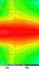
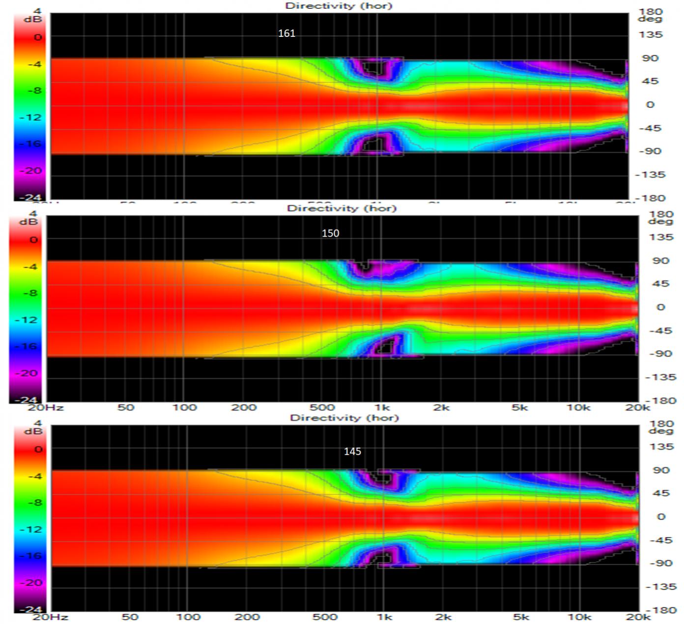
Here is the waveguide vertical map

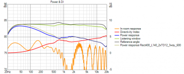
It widens gradually as frequency decreases. You've identified the point where the rim slots take control. I would have loved to have moved the XO a little higher to eliminate that fringing but vertical sidelobes start to appear

I again tried both smaller and larger vertical spacing for the rim slots with very little effect or improvement. DI changed less than .2db.
Despite what I said earlier about wanting a high XO. I reduced the belly in the power response near 1 khz by .5 db by reducing WG XO to 1200 Hz.
Its not ideal; its a compromise, probably tilted too far in one direction.
I hear what you said about narrowing the horizontal; that may be the one thing left to try. I don't want to go too much narrower; I want at least a 60 degree wide forward beam. Is it the waveguide or the rim slots that need to be narrower? the belly in the PR and the peak in the DI are in the rim slot region
It widens gradually as frequency decreases. You've identified the point where the rim slots take control. I would have loved to have moved the XO a little higher to eliminate that fringing but vertical sidelobes start to appear
I again tried both smaller and larger vertical spacing for the rim slots with very little effect or improvement. DI changed less than .2db.
Despite what I said earlier about wanting a high XO. I reduced the belly in the power response near 1 khz by .5 db by reducing WG XO to 1200 Hz.
Its not ideal; its a compromise, probably tilted too far in one direction.
I hear what you said about narrowing the horizontal; that may be the one thing left to try. I don't want to go too much narrower; I want at least a 60 degree wide forward beam. Is it the waveguide or the rim slots that need to be narrower? the belly in the PR and the peak in the DI are in the rim slot region
Attachments

that would narrow the H pattern, if that were desirable. Unfortunately, what one would like to do is narrow the pattern down low without affecting its width up top where beaming occurs. Overcoming beaming is one of the reasons, waveguides at center of arrays are considered.
I've pretty much come to the conclusion there is no escaping Keele's classic rule of thumb for pattern control.
That the lowest frequency of control = 1,000,000 / (width or height in inches) x coverage angle in degrees.
I believe whether it's a horn or a fractal array, to get the same pattern control, overall H & V sizes will end up being fairly close.
That the lowest frequency of control = 1,000,000 / (width or height in inches) x coverage angle in degrees.
I believe whether it's a horn or a fractal array, to get the same pattern control, overall H & V sizes will end up being fairly close.
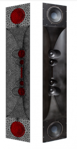
I wouldn't argue with that except for what I see with these rim slot driver arrays. Take a waveguide whose pattern control frequencies are determined by its mouth size. Add a row of small drivers firing through slits on the top and bottom edges of the waveguide, like I did here, and the pattern control frequencies are extended by about an octave for a 10% increase in height.
Stretching the rows of DMA45s out as far as will fit on the baffle and reducing the WG XO to 1 kHz yields this:
That is an ugly peak at 800 Hz but its only .5 db high.
but reducing the XO to 1000 hz narrows the vertical polars below 1 Khz so much that standing height response falls apart so back to the 1500 Hz XO and the larger belly in the power response
Attachments
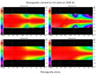
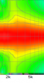
Here is the waveguide vertical map
Is it the waveguide or the rim slots that need to be narrower? the belly in the PR and the peak in the DI are in the rim slot region
The images from that post weren't there but I can see more in the ones you posted later. It looks like the main mismatch is between the horizonal of the rim array and waveguide. So either narrowing the guide to meet or bringing in the array. That maybe easier said than done and a compromise might need to be accepted.
There is a vertical mismatch where the array is gaining directivity and waveguide losing it at different rates. A change in waveguide profile or array position might help but you could well end up chasing your tail there too 😉
If there was a way to move the vertical null from the array higher there would probably be a better match without changing the waveguide.
If you let go of trying to control the ceiling a two way with axisymmetrical guide crossing as low as possible to a similar size woofer seems simple and sensible 🙂
Last edited:
You'd need closer spacing from the rim drivers to catch the null originated from the wave guide letting go of the pattern. Which would mean you'd be creating a Synergy like horn to be able to do that. As it stands, the vertical null is in the worst possible spot if you ask me. It is right where the cross talk dip is in a stereo triangle with an averaged sized head.
One woofer below is going to have a floor bounce null.
My suggestion for array + synergy wouldn't be based on a waveguide of this size.
The fractal array I mentioned would need work too, one would have to have closer spacing to get wider pattern control vertically, which would make it interesting but difficult. But i don't think it would be completely impossible.
So far, except for the lack of horizontal control, Crumboo's array is showing a smoother way to integrate a set of drivers vertically. It has a way less uneven room distribution and it shows in the DI. It may not be perfect but does do a pretty good job.
Last edited:
I thought the main null was due to the arraying of the rim slots rather than a crossover null. I could have that wrong without being able to see all the individual traces.
Crumboo's sims look reasonable, the active FIR is complicated but the foam to reduce the extreme vertical seems promising. The Aries M from Nils Ollerer http://www.hannover-hardcore.de/infinity_classics/!!!/Aries%20M%20Dokumentation.pdf has a good combination of these ideas a bit of foam on the TPL might work well there too.
I remain sceptical of the in room predictions for devices with less drivers sounding as bad as they look.
Attachments
Thank you both for your guidance.
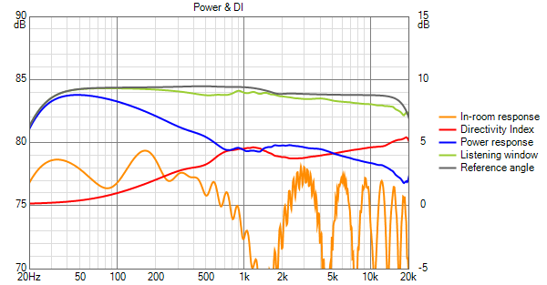
Here is where I am now after optimizing directivity matches as best I could:
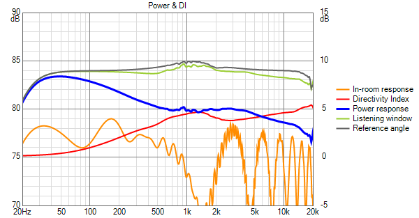
This looks a lot better at reduced vertical scale. When the DI is flattened/plateaued in the XOs region, the peak in the axial is 0.8 db, reduced from 1.8 db. Compromising, I'd have a .4 db peak in axial and corresponding dip in the power response.
How did I get here? I went to bed last night resolving to walk down the array width in small increments to get the best H match - at the 1500 Hz XO. The differences were small but the best match seemed to be with the outermost drivers at +/- 150mm
Going back to the vertical, pattern I looked for the best match at the XO between the rim slots and the td12s. I looked the 600 Hz XO frequency I started with but got an improvement by incorporating some overlap between rim array and woofers
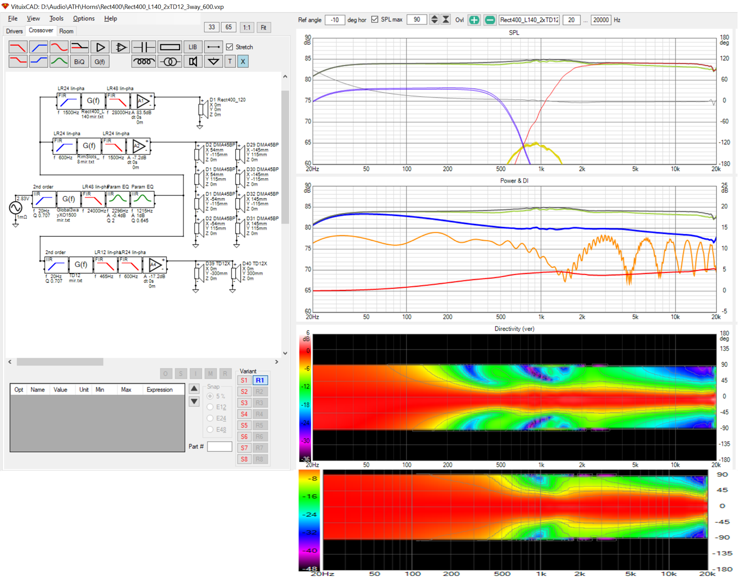
The lower the slope of the woofer low pass, the higher the narrowing of the vertical pattern goes. I put in a narrow slope low pass at 465 Hz, left the original 600 Hz filter in place and made up the energy gap with global eq. This (strangely enough) accounts for much of the improvement.
Chances are I can get a better vertical match by bringing the woofers in closer. They are at the limit given construction constraints for direct radiators. As horizontal slots, they could be closer...I should try that.
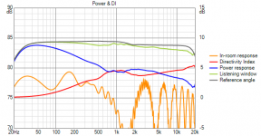
Here is where I am now after optimizing directivity matches as best I could:
This looks a lot better at reduced vertical scale. When the DI is flattened/plateaued in the XOs region, the peak in the axial is 0.8 db, reduced from 1.8 db. Compromising, I'd have a .4 db peak in axial and corresponding dip in the power response.
How did I get here? I went to bed last night resolving to walk down the array width in small increments to get the best H match - at the 1500 Hz XO. The differences were small but the best match seemed to be with the outermost drivers at +/- 150mm
Going back to the vertical, pattern I looked for the best match at the XO between the rim slots and the td12s. I looked the 600 Hz XO frequency I started with but got an improvement by incorporating some overlap between rim array and woofers
The lower the slope of the woofer low pass, the higher the narrowing of the vertical pattern goes. I put in a narrow slope low pass at 465 Hz, left the original 600 Hz filter in place and made up the energy gap with global eq. This (strangely enough) accounts for much of the improvement.
Chances are I can get a better vertical match by bringing the woofers in closer. They are at the limit given construction constraints for direct radiators. As horizontal slots, they could be closer...I should try that.
Attachments


I thought the main null was due to the arraying of the rim slots rather than a crossover null. I could have that wrong without being able to see all the individual traces.
Crumboo's sims look reasonable, the active FIR is complicated but the foam to reduce the extreme vertical seems promising. The Aries M from Nils Ollerer has a good combination of these ideas a bit of foam on the TPL might work well there too.
I remain sceptical of the in room predictions for devices with less drivers sounding as bad as they look.
Main null? Not sure what null you are talking about. Due to arraying? I doubt due to CTC between array elements. I tried twice as many drivers at half the spacing and saw no change other than SPL.
The Aries M is/was an impressive effort for DIY. I would get more out of the article if I read German but I can read the graphs and a few key words here and there.
Crumboo too has done an excellent job. His array is on the order of complexity of my H array, which I have shied away from due to its complexity. I need to review the H array performance to see how much floor reflection sensitivity it has. At the time I thought it was pretty good but wanted something smaller.
As to the room predictions, I've read research that says reflections, especially lateral reflections, are helpful as well research that finds that the first order floor and ceiling reflections do affect timbre and localization. That indicates that my efforts to control the vertical aren't entirely misplaced.
I agree though that Vituix predictions are pessimistic, the higher in frequency the more so. That is why I think pushing the first order floor null out past 1 khz by lowering the speaker/array center helps. At that frequency a good carpet has some hope of absorbing enough to mitigate the null but also because it is more likely to be filled in by the reverberant field.
If you let go of trying to control the ceiling a two way with axisymmetrical guide crossing as low as possible to a similar size woofer seems simple and sensible 🙂
I will go look at your sim of that again (or my own, I think I have a Vituix model somewhere). If I'm going to have a floor null no matter what I do short of a Crumboo or full H-array, that might indeed make sense - but the rim slot array enables a lower crossover.
Attachments
Is that a woofer above and below? If it is, I'd try two woofers below. (and it may not need the one on top)
- Home
- Loudspeakers
- Full Range
- Full range line array for wall or corner placement