First order filters suggests passive but I'm reluctant to take on design construction of a large set of filter boards like you did when I've already invested in multi-channel amps
Depends on what you want to do i guess. I wanted to keep the arrays save for use with my Goldmund amp. 🙂
Before the amplifier test we did, I wouldn't have seen that as a concern. If you have what you have, just make the best of it. You won't know it could/would be different so you're not missing anything, right? 😀
Before the amplifier test we did, I wouldn't have seen that as a concern. If you have what you have, just make the best of it. You won't know it could/would be different so you're not missing anything, right? 😀
I don't deny your results nor can I explain them from an objective measurement point of view.
My use of DSP/active XO is primarily to save time at this stage (and secondarily prejudice against dealing with passives). I have an open mind re' amplifiers. Doing my own amp test will only take place after I've optimized everything else. I think imperfections in my system, including the room, would likely mask differences between very good and even better amps.
My use of DSP/active XO is primarily to save time at this stage (and secondarily prejudice against dealing with passives). I have an open mind re' amplifiers. Doing my own amp test will only take place after I've optimized everything else. I think imperfections in my system, including the room, would likely mask differences between very good and even better amps.
Me neither, I cannot explain it but I don't feel the need to at this moment. I am guessing I like the sound of MOSFET amplifiers, at least in this combination with the arrays. Some combinations just seem to work well together.
I can perfectly understand where you're standing right now. You already have all it takes to take this on with active means. Even though I have had my little amplifier test session with koldby and BYRTT, I don't plan to pursue different topologies in the near future.
There's always something we can optimize further, be it software or hardware, the room, the speaker. As soon as my arrays are back up, I have plenty of things I want to try, one by one. I guess I can continue to play for a long long time to come 😀.
I'm certainly not done with cross talk yet, I just know there's more to be had right there.
By the way, could you also check some distances? I found that my shading worked well to even out the results from 2.5 meter distance up to 3.5 meter.
(the distances of interest to me for various listening positions)
(the distances of interest to me for various listening positions)
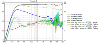
Here is a similar chart for the version with first order filters,

it looks bad but its only a little more than 1 db per half meter; my comment about poor with distance was re' 3m vs 6m thinking about my long L shaped living room + kitchen
it looks bad but its only a little more than 1 db per half meter; my comment about poor with distance was re' 3m vs 6m thinking about my long L shaped living room + kitchen
Attachments
here is a chart for the unshaded line array
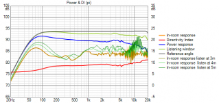
array center is at 1.2m so my standing height is at an offset of -500mm. You can see that shading eliminates most if not all of the HF combing in the direct wave and reduces the variation for +/-200 mm offsets from array center but degrades the standing height response.
array center is at 1.2m so my standing height is at an offset of -500mm. You can see that shading eliminates most if not all of the HF combing in the direct wave and reduces the variation for +/-200 mm offsets from array center but degrades the standing height response.
Attachments

I asked to see it to look at the DI curve, that one is tied into the filtering scheme but can be a good indicator for performance. What I liked about the unshaded array I have is how it centers around the listening axis with it's deviations. I worked real hard to keep that behavior with my shaded version, which also optimized the DI curve further. (if you get what I mean with that, it makes the overall 'perceived' balance similar)
The scale is rather different on the first order version, that threw me off for a moment 🙂.
The scale is rather different on the first order version, that threw me off for a moment 🙂.
I was late coming to the realization that I should pay more attention to the power response and DI curves but I did get there. I should redo shading with that in mind...but if you go back to post 1193, you'll see that there the power response and DI curves were pretty good
Shading my line array is the low hanging fruit but I'm still intrigued by the waveguide with rim slot array. There should be a solution resembling a conventional multi-way waveguide speaker but with improved directivity and extended pattern control. Compared to a Synergy, it should have more than an octave lower pattern control for the same size waveguide but its crossovers will not stay together over as tall a listening window.
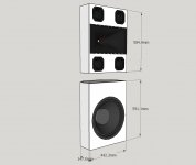
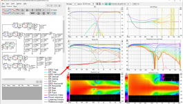
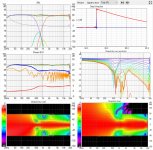
Here is what I have today:
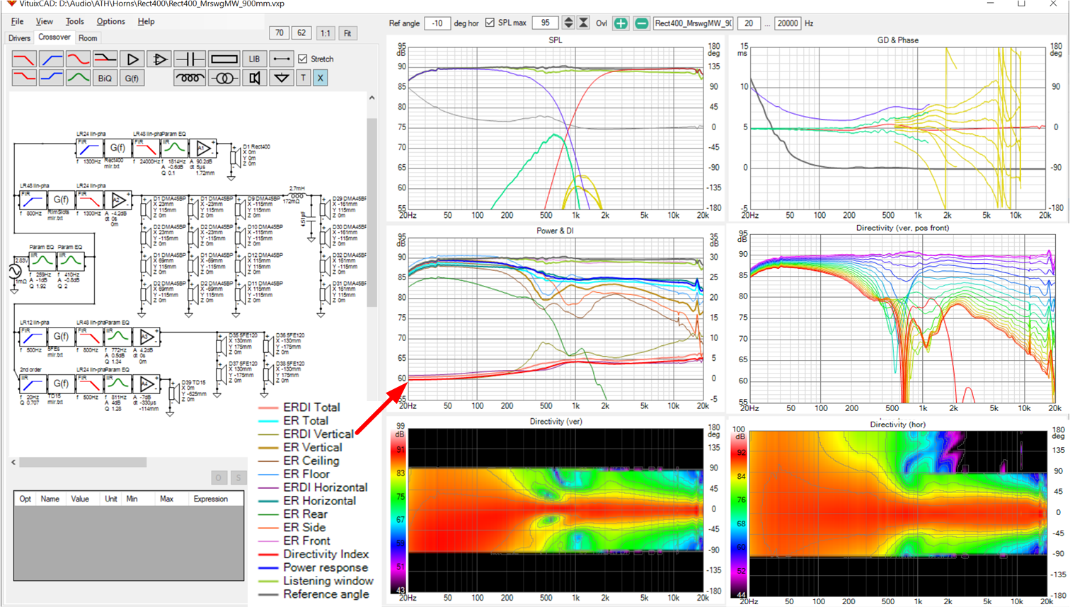
Electrically its a 4-way. There are a number of PEQs in the crossover whose sole purpose is to shape the power response in the 300 Hz to 1 kHz region at a small compromise to the axial response. Axial, power response, and DI curves look good to me. The vertical directivity narrows in that transition region trading off this narrowing for limiting boundary interference nulls in the region.
I purposely left the in-room response off the middle graph as I think it deserves a separate discussion that I would like to have to improve my own understanding. Its evident from my simulations that all such designs (multi-ways) will be sensitive to floor reflections, to a greater or lesser extent depending on the skill with which the drivers have been positioned. Its evident from research/history/experience that this doesn't matter all that much- we can hear the music through the floor reflections. Were this not true, arrays would be a lot more popular. But if relying on in-small-room measurements, it sure is helpful to have the array's near immunity to floor and ceiling influence.
Putting that aside for now, here is what this design would look like with drivers exposed to view:

Here is what I have today:
Electrically its a 4-way. There are a number of PEQs in the crossover whose sole purpose is to shape the power response in the 300 Hz to 1 kHz region at a small compromise to the axial response. Axial, power response, and DI curves look good to me. The vertical directivity narrows in that transition region trading off this narrowing for limiting boundary interference nulls in the region.
I purposely left the in-room response off the middle graph as I think it deserves a separate discussion that I would like to have to improve my own understanding. Its evident from my simulations that all such designs (multi-ways) will be sensitive to floor reflections, to a greater or lesser extent depending on the skill with which the drivers have been positioned. Its evident from research/history/experience that this doesn't matter all that much- we can hear the music through the floor reflections. Were this not true, arrays would be a lot more popular. But if relying on in-small-room measurements, it sure is helpful to have the array's near immunity to floor and ceiling influence.
Putting that aside for now, here is what this design would look like with drivers exposed to view:
Attachments
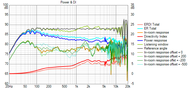
Here is the room response vs offsets data for seated range and seated through standing. Array center is at 900 mm for this design so nominal standing for me is at an offset of -700mm.

Its incredibly flat below 300 Hz, incredibly because this is where the room will dominate, but nevertheless, its as good as or better than the shaded line array simulations there. Above 1 Khz, even smoothed it shows ripple from the 90% floor and 10% ceiling reflection combing.
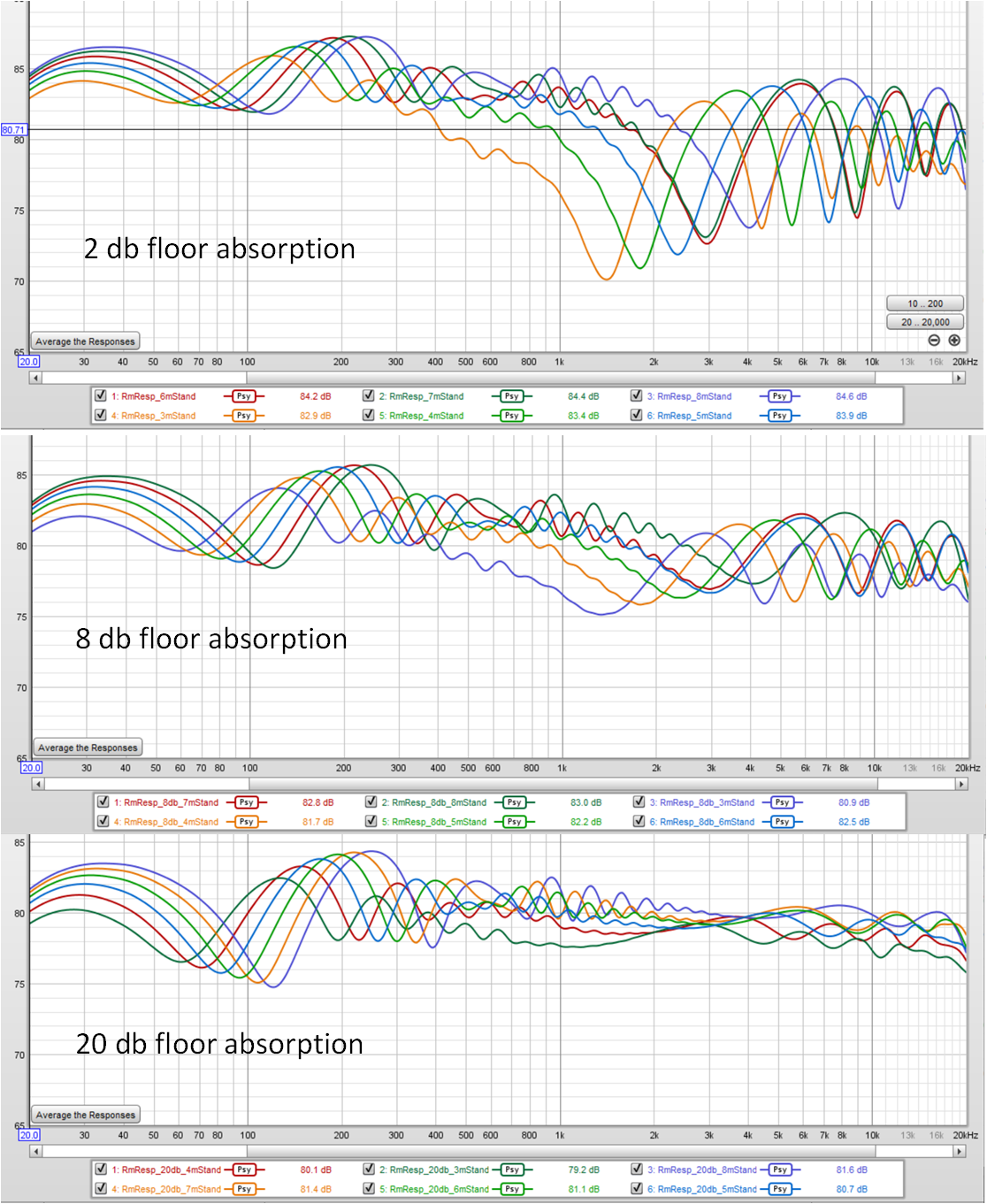
What if I were to repeat those simulations modelling 12 db of floor absorption? That combing ripple above 2 khz would almost disappear. Here is a single such curve:
Only 2 db of ceiling absorption was modelled and the ceiling reflection accounts for most of the residual "grass".
Carpeting evidently would do a great deal to clean up the right half of that room response curve but is it necessary? Or to put it better, aside from its effect on the decay characteristics, how audible would the floor absorption be?
Its incredibly flat below 300 Hz, incredibly because this is where the room will dominate, but nevertheless, its as good as or better than the shaded line array simulations there. Above 1 Khz, even smoothed it shows ripple from the 90% floor and 10% ceiling reflection combing.
What if I were to repeat those simulations modelling 12 db of floor absorption? That combing ripple above 2 khz would almost disappear. Here is a single such curve:
Only 2 db of ceiling absorption was modelled and the ceiling reflection accounts for most of the residual "grass".
Carpeting evidently would do a great deal to clean up the right half of that room response curve but is it necessary? Or to put it better, aside from its effect on the decay characteristics, how audible would the floor absorption be?
Attachments
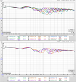

In my living room, standing listening happens at distances well beyond 3m so I produced the following chart. Without floor absorption, the results are disappointing; with it much better but still a lot of ripple.
I'm not sure what to make of these simulations. Vituix includes a boundary simulator that should not be mistaken for a room simulator and no simulator takes into account the brain's ability to hear music through the room effects.
I'm not sure what to make of these simulations. Vituix includes a boundary simulator that should not be mistaken for a room simulator and no simulator takes into account the brain's ability to hear music through the room effects.
Attachments
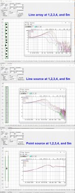
The sims are just floor reflections, but IRL in-room there are many many other reflections more, the sound (and measured response) will be much "better" than these sims. Actually more ripples, but not so "logically" changing per distance.
Anyway, an unshaded line array sums pretty variatingly even without reflections.
Anyway, an unshaded line array sums pretty variatingly even without reflections.
Attachments

Last edited:
That is a good point that the LA depends on the floor reflections for its excellence. Its helpful to line arrays and problematic to others.
After a little thought, I realized why the the comb null deepens with distance above the XO to the waveguide - if you go far enough out, the floor is in the main beam of the waveguide. The vertical narrowing of my waveguide design below 1 khz keeps the floor reflection below standing ear level out to about 5.5m but above 1 khz its almost twice as wide/tall. I don't think I can do much about that without making the waveguide larger.
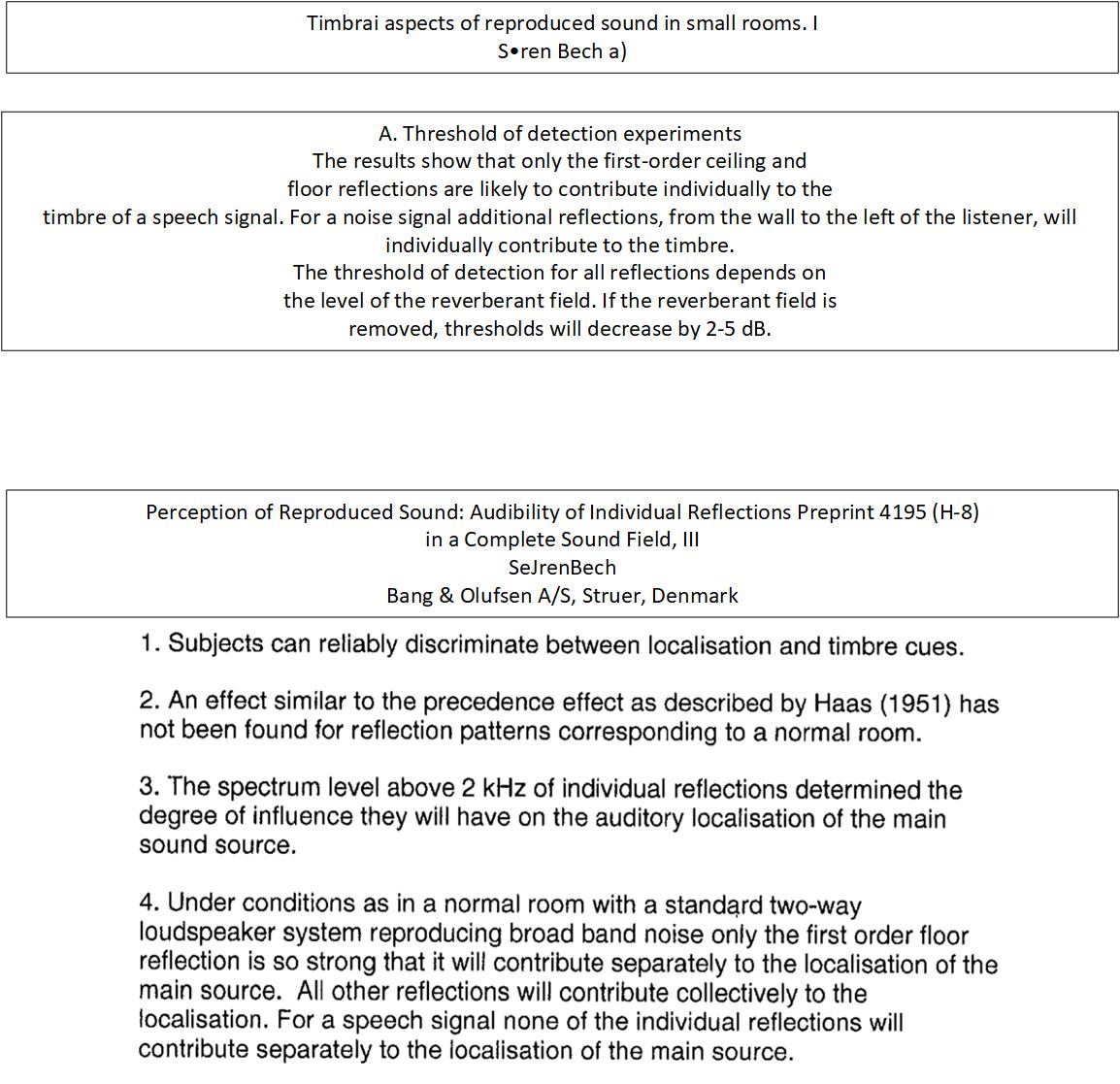
I spent some time reviewing the literature, reading about detection thresholds for both image shift and timbre change, masking by ambient sound field.
After a little thought, I realized why the the comb null deepens with distance above the XO to the waveguide - if you go far enough out, the floor is in the main beam of the waveguide. The vertical narrowing of my waveguide design below 1 khz keeps the floor reflection below standing ear level out to about 5.5m but above 1 khz its almost twice as wide/tall. I don't think I can do much about that without making the waveguide larger.
I spent some time reviewing the literature, reading about detection thresholds for both image shift and timbre change, masking by ambient sound field.
Attachments

What you show there in terms of consistency of directivity is pretty good and compares well to some of the better measuring multiway speakers. Directivity graphs of the GGNTKT and JBL M2 attached. Anything with vertically spaced drivers has difficulty in avoiding a mismatch at some point in the response.Shading my line array is the low hanging fruit but I'm still intrigued by the waveguide with rim slot array. There should be a solution resembling a conventional multi-way waveguide speaker but with improved directivity and extended pattern control. Compared to a Synergy, it should have more than an octave lower pattern control for the same size waveguide but its crossovers will not stay together over as tall a listening window.
I don't put much weight to the reflection estimates. The fact that the floor and ceiling reflections have been shown to modify timbre is a good reason to try and limit them if no other problems are created by doing so. However there is less of a clear indication as to how damaging they are and to what extent in the overall scheme of audible problems they should be placed.
I have tried a few experiments myself where I can tell the difference between two options repeatedly but choosing which one of those I actually prefer is much harder.
Attachments

Lowering optimization priority of reflections leads to different results/choices but if you use enough drivers 🙂 you can have it all, at least within a restricted listening window.
Thanks for the GGNTKT reference. Interesting designs on that website; so nice to see real technical specs published. They certainly get the most out of a limited number of drivers. Perhaps I can learn something from that.
Thanks for the GGNTKT reference. Interesting designs on that website; so nice to see real technical specs published. They certainly get the most out of a limited number of drivers. Perhaps I can learn something from that.
Given that the DMA45s are low passed at 1300 Hz, they can be spaced out, reducing the total to 8. This costs 6 db in max power but there is still more than enough. At the same time, I changed the woofer to a TD12X because I have a pair I've been trying to find a home for ever since I got in on that infamous AE group buy years ago. This allows me to reduce the cabinet depth by 2".
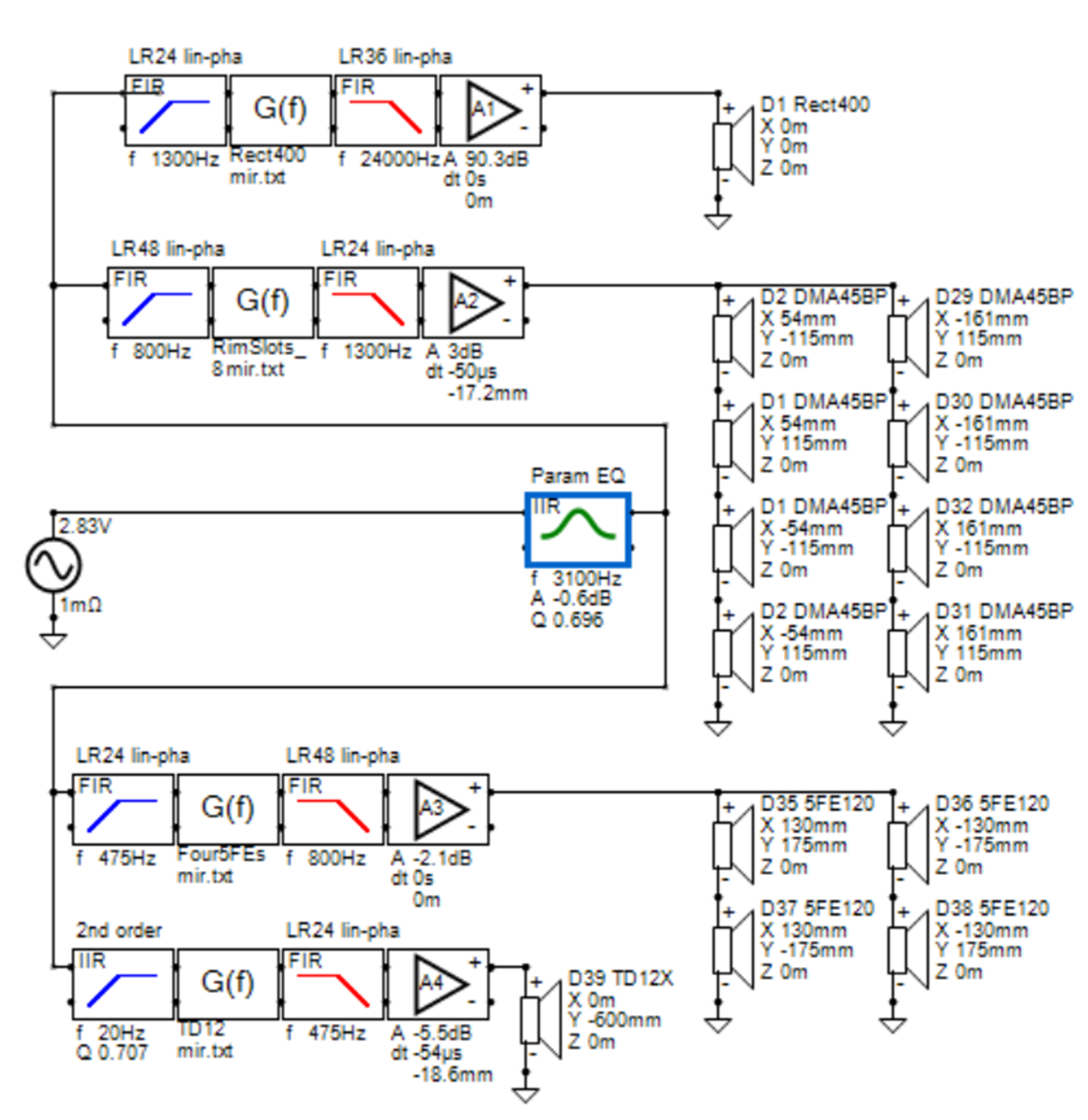
If anything the response is improved, except for perhaps a half octave less displacement on the low end (which I'm not modeling)
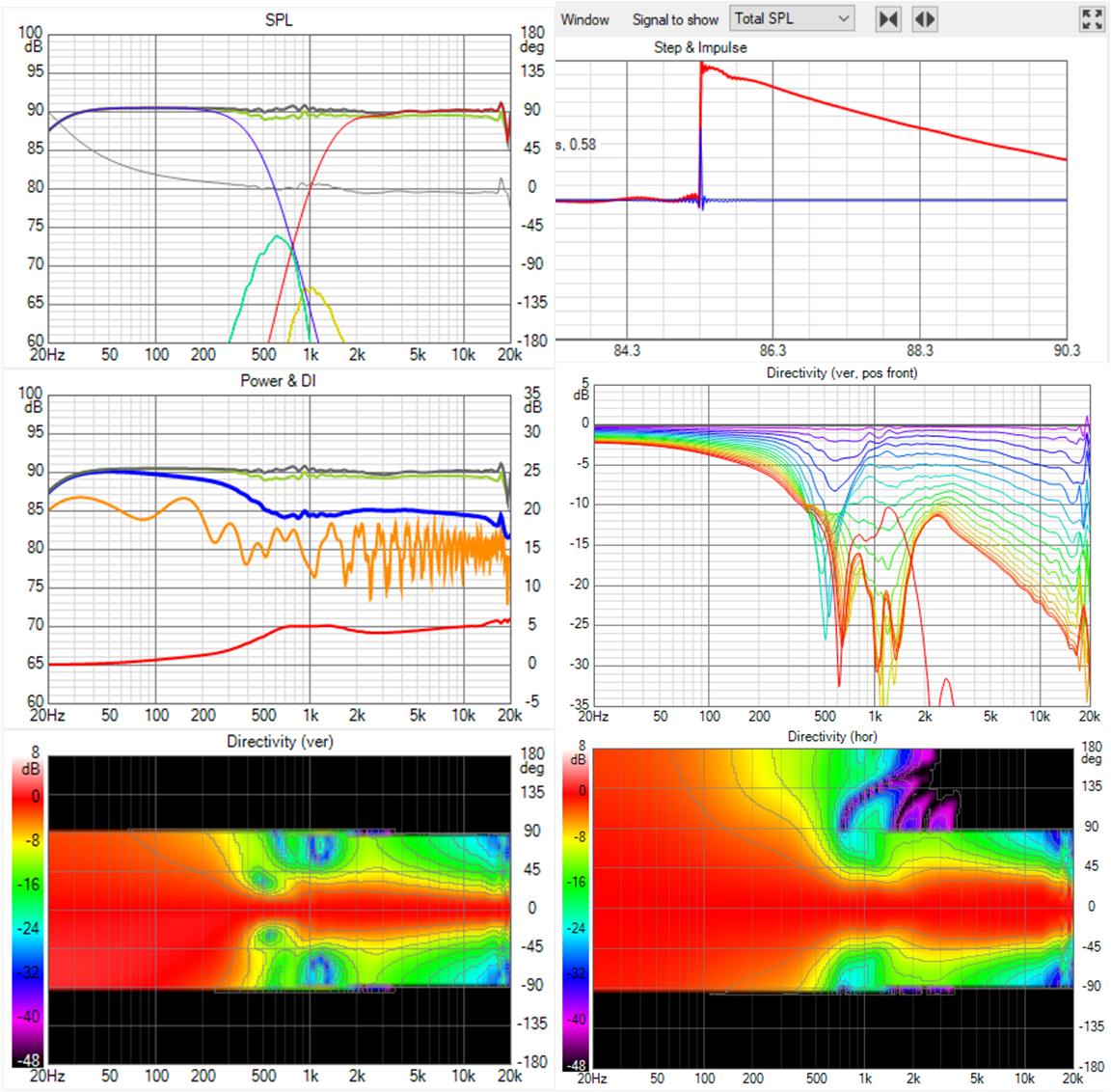
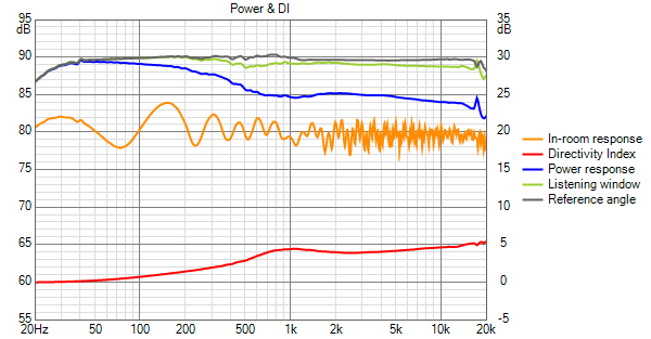
The global EQ PEQ reduces the small hump in the power response due to the waveguide and makes the overall power response look flatter. My next step is to optimize the waveguide...
If anything the response is improved, except for perhaps a half octave less displacement on the low end (which I'm not modeling)
The global EQ PEQ reduces the small hump in the power response due to the waveguide and makes the overall power response look flatter. My next step is to optimize the waveguide...
Attachments
- Home
- Loudspeakers
- Full Range
- Full range line array for wall or corner placement