Free standing speakers? I thought you wanted to keep the corner idea.
I did find the Genelec studio monitor series (with coax) interesting, though in this size limited in output. That's an example that would go with the cardioid woofer setup fluid mentioned. I'd look for something similar in performance with a bigger waveguide top. The verticals and horizontals of the Genelecs seem to perform almost the same.
With your rim drivers I don't like how the 'waist shape' looks with the vertical nulls around ~500 Hz.
I'd figure ~40-45 degree to be where the ceiling reflection is at, when looking from a listeners perspective. The floor being at about ~33 degree on average (depending on listener distance).
That means a lot of difference in off axis behavior between 2-5 KHz/below 300 compared to the 300-800 Hz band, reflection wise in (both) the vertical direction(s).
If that's ok for you, ignore me. But I'd want more similar off axis performance and no nulls in a relative small band (but big enough to maybe cause a tonality problem i.m.h.o.).
The corner speakers are great and with them you don't benefit from cardioid unless you develop a need to place them somewhere else. If you are nestled in tight to the corner, you can't even change the toe in. OTOH, with cardioid you can put them in/near near the corner as well as out in the room. The only problem with the 4x12" is you have 4 woofers in a single box instead of 2 single woofer boxes to stack up. Its exciting to have a choice but I'm really reluctant to sign up for so heavy a solution.
If I could increase waveguide size without limit it would be easy. Funny you should mention Genelec as they also use rim slots. Its not the rim slots that are the problem; its the waveguide size. If you want small/reasonable size waveguide then some compromise is inevitable. The question is what? There is a lot of guidance out there starting with Toole and finishint with Fluid and Kimmosto that floor reflections are of secondary importance and to optimize both axial and power responses.
The waist shape is a perfect example. I can widen the woofer vertical response so it matches better with the waveguides but if I do then the floor and ceiling reflection nulls grow significantly. The ideal solution would be to instead narrow the waveguide pattern but that requires a proportionate increase in the waveguide size. Or it requires cardioid or beamforming up to 1.5 kHz or so.
Was the waveguide in this post: https://www.diyaudio.com/forums/full-range/337956-range-line-array-wall-corner-placement-130.html#post6654334 a bigger one? As the floor bounce would be at 300 Hz, the reason why I suggested adding a (low placed) woofer. I know you simulated that already, but not like I would have done.
I would run the pairs surrounding the waveguide with a dip at ~300 Hz (as everything they blast in there would only add to that null) and let the third, bottom woofer have a peak there in that same region. In other words, act active and separate from each other, that is, if the bottom woofer (and it's floor mirror) would not show to have any (obvious) trouble at or around 300 Hz. That was the idea I was playing with.
I am all for free standing speakers, as aiming them can have quite an influence on the result at the sweet spot of interest. Plus one can play with how they react with the room. Two corner placed speakers would always have similar weaknesses (and strengths).
Last edited:
The waveguide in that post was Fluid's 472mm dia. HF1440 waveguide.
The problem with a simple notch at 300 Hz is that the floor null moves with position - from 300 Hz at 3m listening distance to ~410 Hz at 4m and 430 hz at 5m. For position independence, the notch needs steep slopes but a fairly wide bottom, which is hard to do.
It would be simple to add that floor level woofer and cross between upper pair and lower pair at 250 Hz or so - but then the upper woofers wouldn't contribute below 150 Hz where you need their displacement. A more complicated XO would sum that band into the upper woofer pair. Instead, I changed the upper woofers to pairs of 5" drivers and then added a 12" woofer at floor level. That gave me the response of https://www.diyaudio.com/forums/full-range/337956-range-line-array-wall-corner-placement-130.html#post6655457 and the following post.
These are incrementally better with a 15" woofer at the floor and better on horizontal axis then 10 degrees off as apparently was shown.
Right after that train of thought, cardioid came along.
I tried the triple 12s and its not bad. The response suffers between 500 Hz and 1.2 kHz because of the CTC of the 12's flanking the waveguide. With rim slots flanking the waveguide CTC for the bridge drivers playing perhaps 400 Hz to 800 Hz is 145 mm, which should be even better...
You can see what I meant by more complex XO summing in the lowest octaves to the upper woofers.
Wesayso's complementary peak/dips over the notch band are the blue traces in the top graph. After capturing the screen, I raised the XO between upper pair and lower woofer from 400 Hz to 500 Hz and verified floor null mitigation out to 6m listening distance,
Attachments
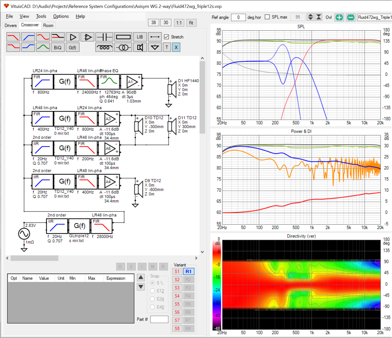
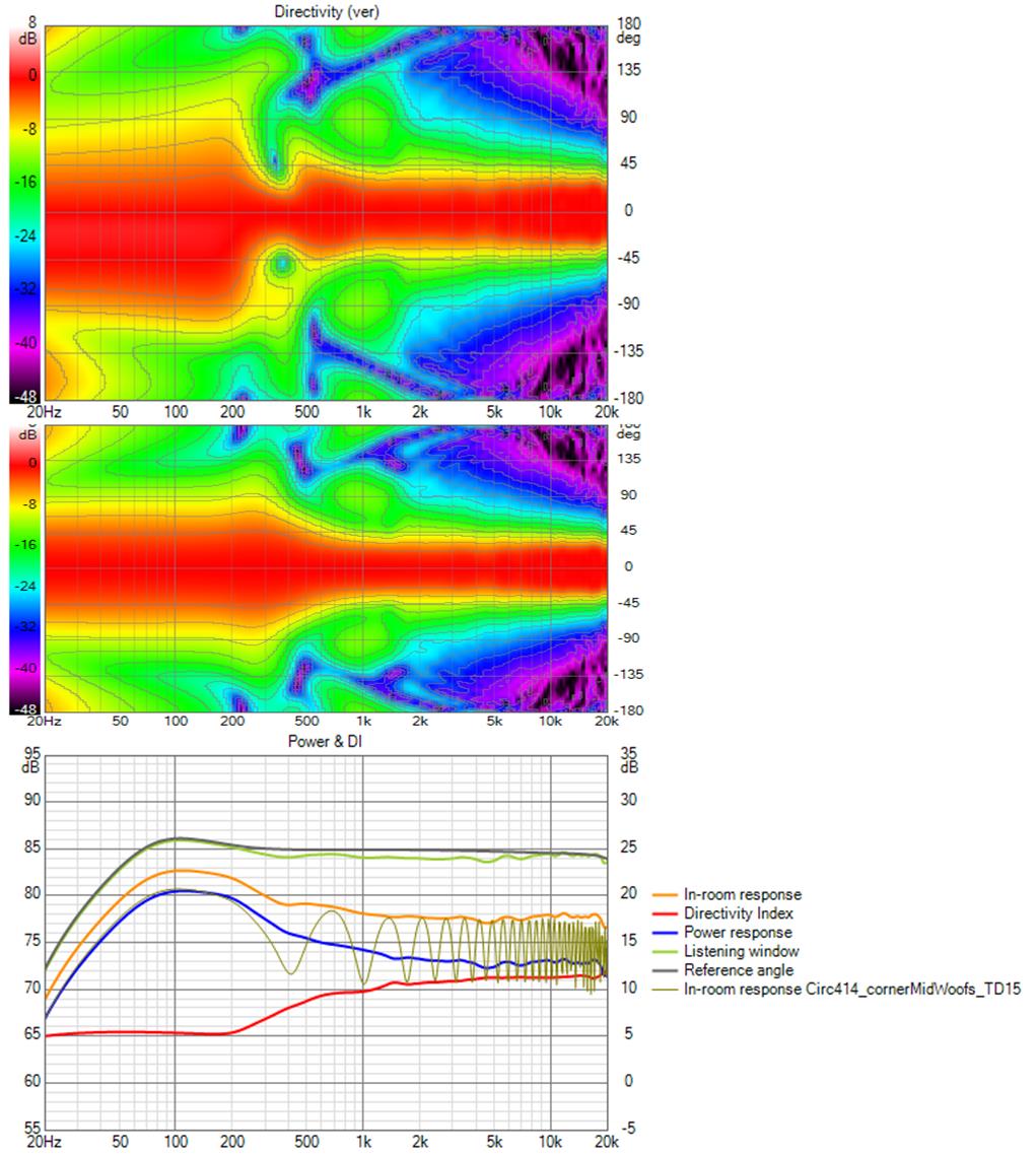
This seeming tail chasing exercise has circled back to the 2xTD12 stacked below the waveguide with rim slots - except I am making progress. I found a way to adjust the power response in the crossover region
The the upper woofer is overlapped with both the rim slots and the waveguide up to 800. Trimming the rim slot drive level trims the power response/DI in the problematic area. I have equalized flat and have just 1 db or so belly in the power response. If I were to split the difference between it and the axial response, I doubt it would be audible.
The light grey trace in the top graph is the axial with the global eq off. It shows the overlap. The light grey trace in the middle graph is the in-room response with floor and ceiling reflections enabled.
Attachments

New waveguide, new bridge/rim approach, cardioid bottom
I've been working on several fronts trying to produce a system with flat axial response and smooth monotonically falling power response of course with good polars and minimal boundary interference.
Cardioid with small side woofers is a worthwhile addition to the mix because it makes the result relatively location insensitive.
A new waveguide was in order because (I eventually realized) it was its slightly rising off axis response in the upper midrange that resulted in the small belly in the power response I had been unable to eliminate. I finally found the knob to twist in the ATH script and made progress there. With axisymm waveguide I could do an ATH/ABEC iteration about every 5 minutes.
The horizontal rim drivers weren't working optimally. CTC was too great to allow the response to extend high enough to meet the waveguide. It was a problem with both HF1440 round and my Rect400.
The new waveguide/CD reduced/eliminated the belly in the PR but needed something to bridge the gap to the woofer, even assuming a 1/4"CD. The key change was to put the bridge drives on +/- 45 degree diagonals around the axisymmetrical waveguide where they extended both H and V pattern control.
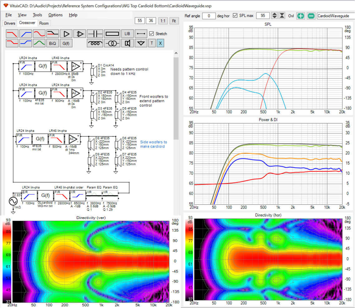
Finally, this emerged:

The new waveguide is 414 mm diameter and has 4 4" drives just outside its rim on diagonals. These extend both horizontal and vertical directivity to better meet with the 15" woofer near floor level. There are 5" woofers on the cabinet sides at woofer height with DSP filters creating an active cardioid response above 100Hz or so. The 100 Hz high pass filter in this chain makes the response omni below its cutoff and allows those 5" woofers to suffice. Omni below 100 Hz preserves the front woofer's displacement for reproducing low notes.
I've been working on several fronts trying to produce a system with flat axial response and smooth monotonically falling power response of course with good polars and minimal boundary interference.
Cardioid with small side woofers is a worthwhile addition to the mix because it makes the result relatively location insensitive.
A new waveguide was in order because (I eventually realized) it was its slightly rising off axis response in the upper midrange that resulted in the small belly in the power response I had been unable to eliminate. I finally found the knob to twist in the ATH script and made progress there. With axisymm waveguide I could do an ATH/ABEC iteration about every 5 minutes.
The horizontal rim drivers weren't working optimally. CTC was too great to allow the response to extend high enough to meet the waveguide. It was a problem with both HF1440 round and my Rect400.
The new waveguide/CD reduced/eliminated the belly in the PR but needed something to bridge the gap to the woofer, even assuming a 1/4"CD. The key change was to put the bridge drives on +/- 45 degree diagonals around the axisymmetrical waveguide where they extended both H and V pattern control.
Finally, this emerged:
The new waveguide is 414 mm diameter and has 4 4" drives just outside its rim on diagonals. These extend both horizontal and vertical directivity to better meet with the 15" woofer near floor level. There are 5" woofers on the cabinet sides at woofer height with DSP filters creating an active cardioid response above 100Hz or so. The 100 Hz high pass filter in this chain makes the response omni below its cutoff and allows those 5" woofers to suffice. Omni below 100 Hz preserves the front woofer's displacement for reproducing low notes.
Attachments

Here is what the response would look like with the 100 Hz high pass in the filter chain for the side woofers disabled:
But of course you can't disable the high pass filter because that would over-work the 5" side drivers. The slide makes clear the cost of extending the cardioid response all the way down. Better to keep the system close enough to walls to avoid boundary nulls. That isn't hard cardioid down to 150 Hz or so.
But of course you can't disable the high pass filter because that would over-work the 5" side drivers. The slide makes clear the cost of extending the cardioid response all the way down. Better to keep the system close enough to walls to avoid boundary nulls. That isn't hard cardioid down to 150 Hz or so.
Attachments
There are still several things to do before declaring victory. The primary thing though is to model the full cabinet in ABEC which will no doubt lead to a number of waveguide and cabinet iterations.
This simulation was done in free standing mode for the waveguide with its mouth rolled back 180 degrees. A waveguide modelled free standing shows extended pattern control compared to one modelled infinite baffle, even a waveguide without a mouth rollback. This latter part is surprising because my initial thought was it was the rollback that was responsible for the added pattern control. I also thought a large baffle would support the response at the low end as in baffle step. Regardless, I need to model this waveguide plus actual baffle and cabinet free standing to trust the simulation results as any more than an indication that the concept is sound.
Doing that requires that I finally learn Fusion360. I have to give up on Sketchup for ABEC. The only way to use it, it seems, is to manually mesh what you draw and that takes too much time, especially if multiple iterations are required. I have made some progress in that direction but I'm not there yet; need a consistent, concerted effort to burn the Fusion moves into my mental muscle memory.
I think this is heading back in the right direction 🙂Finally, this emerged:
Cardioid with small side woofers is a worthwhile addition to the mix because it makes the result relatively location insensitive.
This is similar to what I was going to try to simulate myself.
The small drivers on the side just so happens to fit nicely with the Sica woofers I bought. I was thinking the 15 up high with the side woofers and the sub driver on the back at the bottom.
Did you just use the diffraction tool to model the baffle sides on the 5 inch woofers?
Is there a reason you chose Linear phase crossovers for the side drivers?
I haven't paid much attention to the schematics before is there a reason for all the 20Hz high pass blocks?
This simulation was done in free standing mode for the waveguide with its mouth rolled back 180 degrees. A waveguide modelled free standing shows extended pattern control compared to one modelled infinite baffle, even a waveguide without a mouth rollback. This latter part is surprising because my initial thought was it was the rollback that was responsible for the added pattern control. I also thought a large baffle would support the response at the low end as in baffle step. Regardless, I need to model this waveguide plus actual baffle and cabinet free standing to trust the simulation results as any more than an indication that the concept is sound.
There is always more pattern control in a freestanding or baffled waveguide. The rollback doesn't really extend the pattern control beyond making the device bigger but it is very consistent. The depth of the cabinet and size of the front baffle can have quite a dramatic effect on the polars in both positive and negative ways.
The next stage will start to get tricky and time consuming because you will have to move to half symmetry and the physical size of that cabinet is going to be an issue for the element count.
We've both been talking to Kimmo about cardioid. And your Sica's are comparable to my 5FE120s although the 5FEs have a bit more excursion and I've only bought 2 so far.
I used Vituix SPL trace and diffraction tools to create the directivity files for the side woofers. For the next step, I should redo that and model the actual side baffle dimensions, which I don't yet know.
I used linear phase filters for the side drivers with one exception - the low pass filter that creates the delay needed to get a cardioid response. The reason being so that their delay wouldn't contribute to that delay. My other reason for doing that is habit. Mark100 endorses the process (described below).
My approach to flattening a driver's response for a crossover is to use Vituix's mirror function, which is equivalent to impulse response inversion. Flanking each mirror filter are high pass and low pass filters that apply the slopes at each end. At the very low end, 20 Hz, I want a 2nd order roll off like a sealed woofer would have so I use a 20 Hz IIR filter. That expresses my intention to equalize flat to 20 Hz in the so called real world, if I ever get there 🙂
Last edited:
I think I was mixing up the graphs too which didn't help. I see now that the Gf block with txt file is the inversion EQ so it all makes sense.
speaking of making sense - I just removed the 20 Hz high pass filter in the filter chain for the side woofers. Its not needed given the 100 Hz high pass filter also in the chain. After re-doing the global eq, the results are the same.
Hi guess, have you noticed this review of Perlisten towers?
Perlisten S7t Tower Loudspeaker Review - Are these Endgame? | Audioholics
It has similar narrow vertical directivity, added with bass response going down to 20s. Editors like it...
Perlisten S7t Tower Loudspeaker Review - Are these Endgame? | Audioholics
It has similar narrow vertical directivity, added with bass response going down to 20s. Editors like it...
Last edited:
Nice find! That's indeed quite similar and usually an uncommon feature in commercial speakers.
I need 2 pairs of their tweeter/mids! 😀
Perlisten speakers | Page 4 | Audio Science Review (ASR) Forum
A tweeter array with 112 dB sensitivity would be quite welcome. 🙂
I need 2 pairs of their tweeter/mids! 😀
Perlisten speakers | Page 4 | Audio Science Review (ASR) Forum
A tweeter array with 112 dB sensitivity would be quite welcome. 🙂
I had not noticed those; I had seen and been impressed by Kii, which is about the same price with bass but without a bass array but gives you Cardioid and includes the amps and DSP. The Kii bass array likely puts the price into the stratosphere (status-sphere); I didn't even look it up.
Perlisten doesn't attempt to control the horizontal directivity below the tweeter and its bass isn't cardioid and so it will be subject to boundary interference.
I'm wondering if I can use side drivers on the waveguide to get the same pattern control there in a narrower package.
Perlisten doesn't attempt to control the horizontal directivity below the tweeter and its bass isn't cardioid and so it will be subject to boundary interference.
I'm wondering if I can use side drivers on the waveguide to get the same pattern control there in a narrower package.
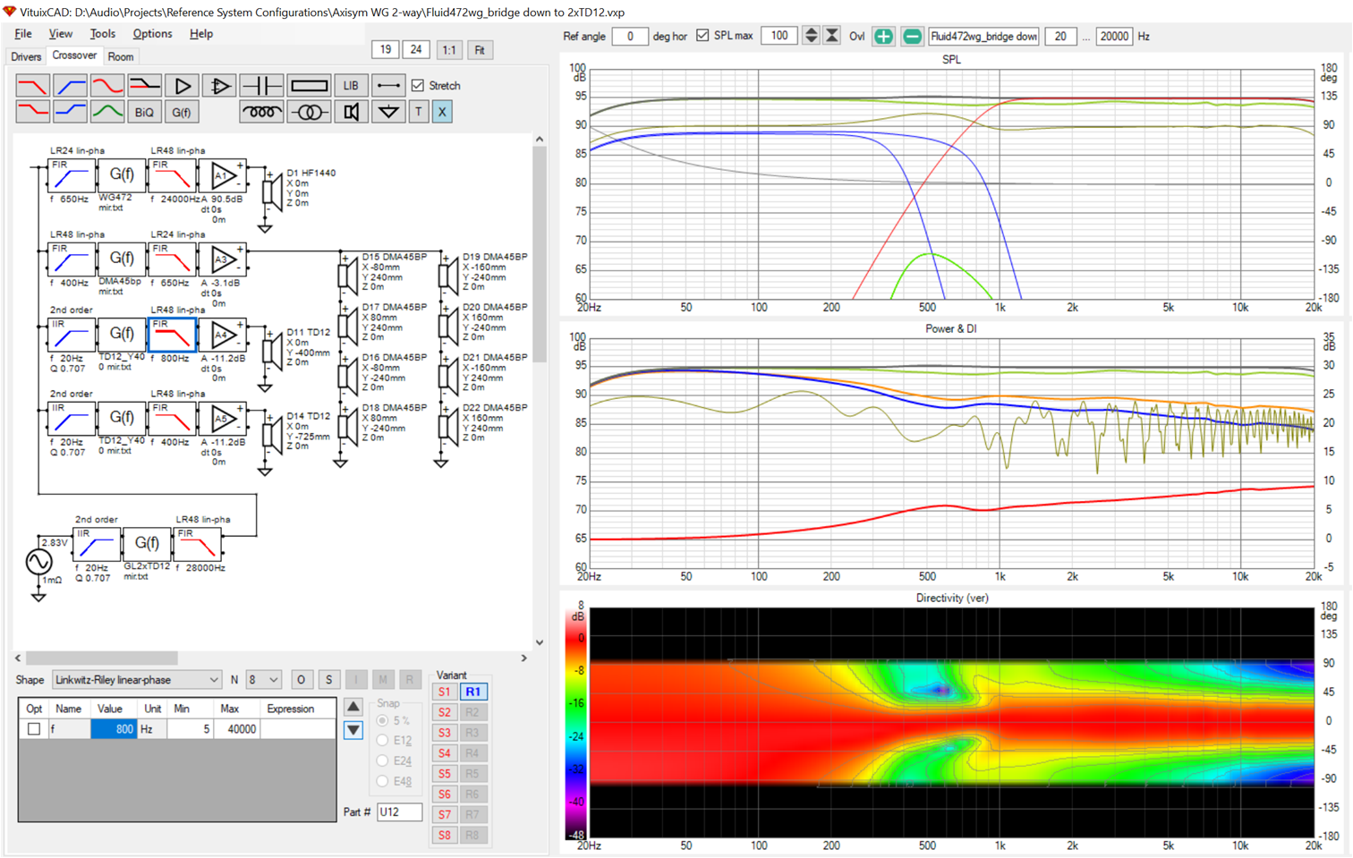
swapping in two TD12s below the waveguide for the single TD15, I get an improved vertical response - less narrowing at the crossover which translates to good standing response even at 3m listening distance

Notice also that pattern control is extended down almost to 60 Hz with the side woofers. It looks also like 4FE35s are a viable choice for side woofers and easier to fit in the space.
Notice also that pattern control is extended down almost to 60 Hz with the side woofers. It looks also like 4FE35s are a viable choice for side woofers and easier to fit in the space.
Never mind that one for now. Turns out adding side woofers to the waveguide is a really hot idea!
I do cardioid around the waveguide and front woofers, I get a "top" that is good - meaning directivity controlled - down to 100 Hz. A waveguide that holds pattern down to 1 khz is about 60% the size of what I've been modelling. Add you favorite subwoofer or stack of Purifi 6.5" and you are done!
For response down to 100 Hz, those front woofers should really be 5", not 4". If woofer good to 200 Hz, the 4's are more than adequate.
Attachments
Last edited:
- Home
- Loudspeakers
- Full Range
- Full range line array for wall or corner placement