That baffle shape will not work as well as a flat baffle or an actual rollback. Putting a big roundover on it would help, it's the cylindrical shape behind that creates an issue.I played with the Sketchup drawing today.
There is only so much you can do aesthetically. I hid the rim driver holes (1cm) diameter in the waveguide roll back and gave the cabinet a round top.
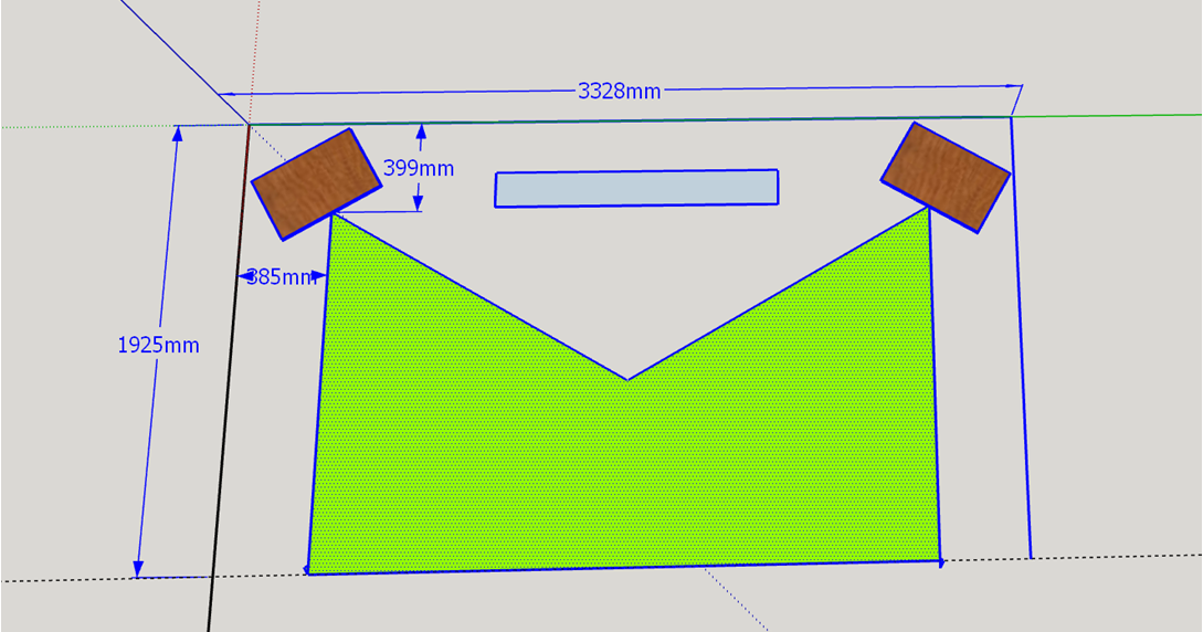
Have you simulated the corner space? I would have thought the cardioid needed some room to breathe.The grey triangle shows how it fits in a corner.
There was no driver EQ, that is the raw response of the drivers in fairly small closed boxes. There is nothing much below 100Hz to keep 🙂 That is where I hoped the rear sub driver would come in. I was trying to keep it simple and get the pattern working as I got all sorts of rubbish the first time I tried. If I did EQ the Faital the natural rolloff of the Sica's Enclosure would probably be enough to made smaller to target it.Yes, that looks good; except for the lack of response below 100 Hz. I didn't want to give that up.
I will have to try various baffle shapes in ABEC...
What exactly was your sim? I thought it was just front and rear woofers but your response mentions Sicas. Are you using them on the sides?
Cardioid needing room to breathe? I don't know; I'll have to see. I can give it 1m or so If I have to. Vituix tells me a little bit about operation from a corner but not enough to make me completely comfortable. It would tell me more if I took the time to ask it (i.e. record response over +/-90 degree reference angles)
What exactly was your sim? I thought it was just front and rear woofers but your response mentions Sicas. Are you using them on the sides?
That sim was a 15" Woofer with two Sica five inch side woofers
Whether having near boundaries interferes with the pattern negatively.Cardioid needing room to breathe?
As the baffle I had thought about the idea of side woofers being placed either side of a standard rectangular at waveguide height rather than being embedded like you used in one of the iterations.
The depth of a regular enclosure helps to maintain directivity to a lower frequency if you can't use a true rollback. Anything in between simulates like a worse compromise to me.
Attachments
Last edited:
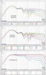
The previous one was quite mild being not that much different to a 15" woofer by itself and I hadn't cascaded the low pass filters.
This one gets a pretty flat DI over the range of interest but the normalized polar is less pretty. Same arrangement different filters, level and delay.

This one gets a pretty flat DI over the range of interest but the normalized polar is less pretty. Same arrangement different filters, level and delay.
Attachments
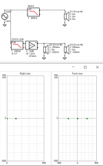
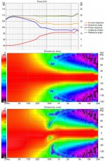
These 3 graphs are Vituix's answer to the question re' the effect of the proximity of the walls. The bottom graph gives the waveguide's response vs angle w/o regard to the walls. Keep in mind its a +/-30 degree waveguide. These are 10 degree steps with response normalized at 10 degrees off axis.
The top graph shows the in-room response with 12 db absorption on the walls. The middle graph is the same but with 2 db wall absorption.

These show I don't need wall absorption as the responses within the +-30 degree beam are more highly correlated without it.
The top graph shows the in-room response with 12 db absorption on the walls. The middle graph is the same but with 2 db wall absorption.
These show I don't need wall absorption as the responses within the +-30 degree beam are more highly correlated without it.
Attachments
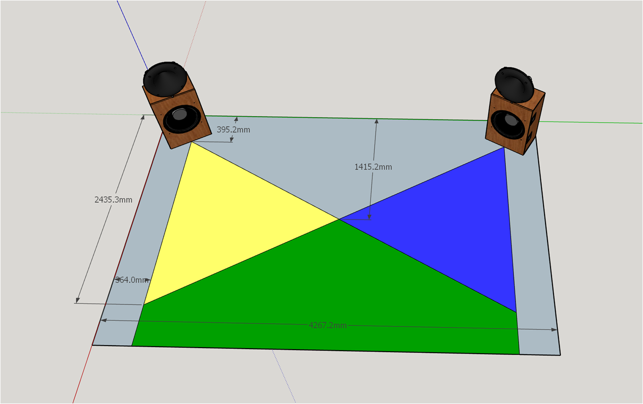
Doing the room response made me think of room placement. The room response was taken with 45 degree toe-in which of course doesn't work with a 60 degree beam. You toe the speaker in so the edge of the beam is parallel to the side wall. With these box dimensions, you find you need to sit with your head 400 mm from a side wall and >~2m from the front wall.
Attachments

A better room placement diagram:
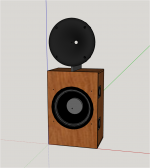
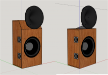
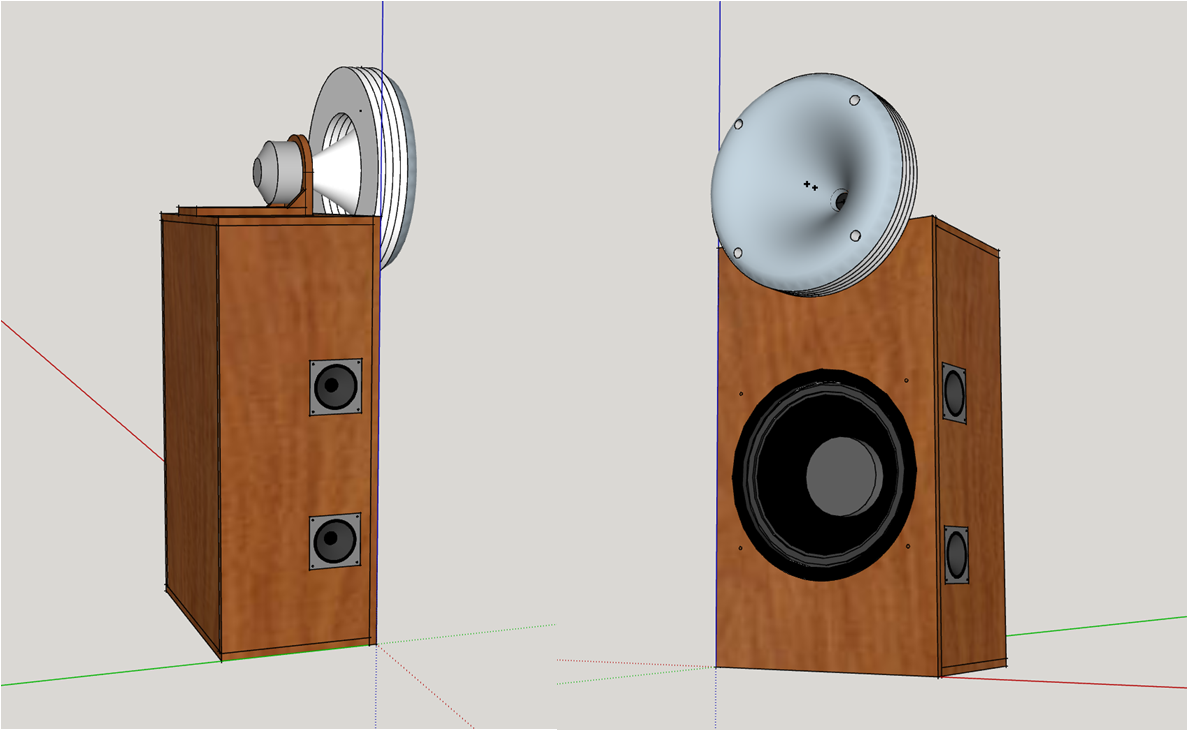
This one uses the full cabinet image. The rolled back wavelength is suspended 2" above the woofer cabinet almost invisibly. It has 4 rim drivers on its back, playing through the rollback. Those drivers will have 3D printed cups to close their backs.
I deleted the upper side woofers with almost no discernable effect most of which was repaired by increasing the vertical separation of the remaining side woofers.
I would like to round over or at least bevel the cabinet edge(s) under the waveguide but I'm uncomfortable at the thought of applying veneer around the corners of a rounded edge. ?
There seems to be enough vertical beamwidth to allow the WG to be another 100 mm higher. How much is enough ?
Attachments
Is this for aesthetic reasons? The rolled back waveguide is pretty insensitive to what is around it. A square cornered cabinet will likely give virtually the same performance in this setup.I would like to round over or at least bevel the cabinet edge(s) under the waveguide but I'm uncomfortable at the thought of applying veneer around the corners of a rounded edge. ?
You can roll the veneer if the grain is up and down then it will bend to the left and right but not so well in the direction of the grain. The paper backed veneers are much easier to use and can be softened to help with the bending.
Wouldn't you just want the CD to be at seated ear height?There seems to be enough vertical beamwidth to allow the WG to be another 100 mm higher. How much is enough ?
What I wrote about the veneer might have been confusing. It will bend in all directions particularly if it is thin, but it will sometimes bend tighter across the grain. The problem with that is it might also split or open up too much and look ugly.
Re' vertical beamwidth - I'm glad to hear that a rolled back waveguide is relatively insensitive to its surroundings. I was wondering about that. If so, then of course I want WG center at ear height. But now I'm considering rolling back the waveguide 180 degrees into a baffle. Then I can extend the baffle up behind the waveguide and use all the volume behind it for the woofer, which could use some more volume given what has been taken from it for the side woofers. It also might allow some reduction in depth.
What do you think of that?
Re' veneer - Given my limited skill and experience (used peel and stick a couple of times), I would be better off with solid wood edges where I want to round over. I hadn't thought of that when I posted.
What do you think of that?
Re' veneer - Given my limited skill and experience (used peel and stick a couple of times), I would be better off with solid wood edges where I want to round over. I hadn't thought of that when I posted.
Last edited:
I've thought a lot about the issue you are having (big multiway on a corner) and getting rid of ports and using a smaller than optimal enclosure can help optimize other aspects of the system without too much audio penalty on the lows.
Decent SPL and low end extension can be had with sealed enclosure, pro woofer, DSP and some extra power from the amp. The compromise in home use is mostly in the cost, unless you already planned for the DSP and separate amp for the woofer. I would prioritize the cardioid thing you have going over optimal woofer box volume and rely on the electronics to get the lows.
Decent SPL and low end extension can be had with sealed enclosure, pro woofer, DSP and some extra power from the amp. The compromise in home use is mostly in the cost, unless you already planned for the DSP and separate amp for the woofer. I would prioritize the cardioid thing you have going over optimal woofer box volume and rely on the electronics to get the lows.
Last edited:
I agree with your analysis 100%. I made the $commitment to active speakers a long time ago. I already have the amps and DSP (via Jriver and a Motu sound card) . As it stands, my best amps are borderline big enough for the woofers, thus my concern about box volume.
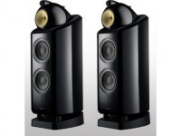
I think a baffle would have a fairly significant effect but I haven't simulated it to have a direct answer. You could angle the woofer cabinet up under the waveguide a la B&W 802 D3. I like the idea of something similar with a waveguide where the mid and tweet is.But now I'm considering rolling back the waveguide 180 degrees into a baffle. Then I can extend the baffle up behind the waveguide and use all the volume behind it for the woofer, which could use some more volume given what has been taken from it for the side woofers. It also might allow some reduction in depth.
What do you think of that?
Attachments
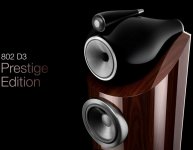
I hope you pick the previous 802D style as inspiration, I think the new one looks "off" in comparison to those 😉.

Attachments
Last edited:
I'm afraid I could never match either of those finishes. When it comes to tilt top vs flat top at my level of woodworking skill, its a question of which is ugliest.

The one on the left needs only about half the power at the low end of the equalization curve but it has a kind of looming presence. I think I'll just buy a bigger amp if it turns out I need one.
The one on the left needs only about half the power at the low end of the equalization curve but it has a kind of looming presence. I think I'll just buy a bigger amp if it turns out I need one.
Attachments
The design continues to evolve:
Having drawn that, I needed to model the cylindrical back added to the waveguide to enclose the rim drivers. After several hours in CAD that accomplished little more than learning a little more Fusion360, I realized that all I needed to do was to modify the nodes.txt file that defines the wg profile. This is best done in a spreadsheet where you can graph to see the effect of your changes.
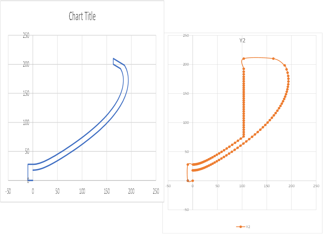
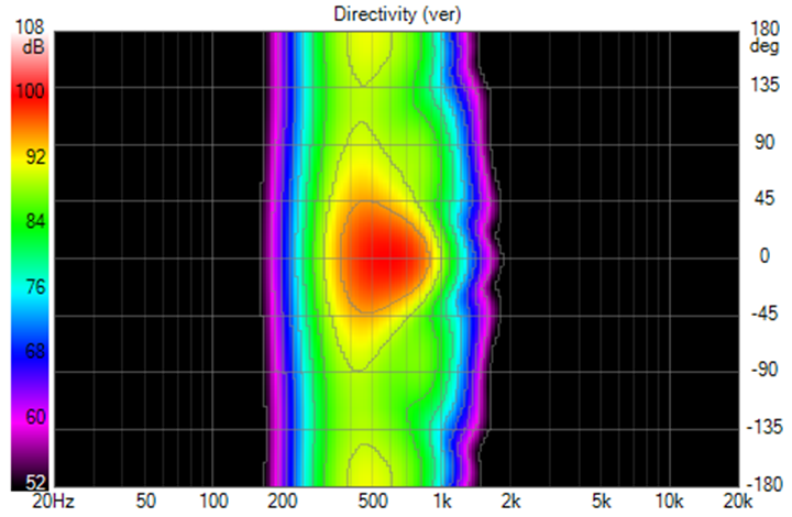
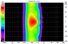
There was very little change to the Vituix simulations, a slight improvement in the H polars:
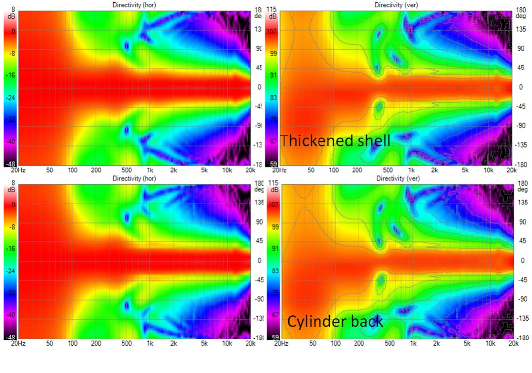
Having drawn that, I needed to model the cylindrical back added to the waveguide to enclose the rim drivers. After several hours in CAD that accomplished little more than learning a little more Fusion360, I realized that all I needed to do was to modify the nodes.txt file that defines the wg profile. This is best done in a spreadsheet where you can graph to see the effect of your changes.
There was very little change to the Vituix simulations, a slight improvement in the H polars:
Attachments


Hi, sorry I haven't followed the whole path you are taking so I'll ask did you ever consider using resistance enclosure (cardioid) instead of the quad side woofers? Looks like you are using 2nd order low pass for the side woofers, which seems to be the slope with resistance ports as well? Bass response might be a bit less, but the box could be smaller which seems to lessen diffraction effects if any concern about those. Cost would be you might have to add a sub. And I don't know if this kind of box can be simulated so some extra prototyping required.
Anyhow, been thinking about boxes lately and it looks like the smaller the better and trade-off being less volume so less bass from a driver. Making passive cardioid box(es) between about the schroeder frequency and the wave guide seems to me the most logical solution currently. Below about schroeder frequency bass boxes don't have to be that close to the "main" speaker which means less disturbance both sonically and visually since one could hide them into furniture 🙂 Would get the speaker closer to the corner as well. You only need to size each way (subs, cardioids and the waveguide) to support your SPL requirements and there probably is perfect size to have the reference level come out nicely.
edit. Thinking of it, a small bass box close enough to corner and resistance vents on top and bottom would be nice? Controls vertical directivity while horizontal is taken care by the room walls. Anyway, it is fun to follow what you end up with at the end and how close to simulations it eventually measures 🙂
Last edited:
With that bass cabinet and the wg set forward as shown, its possible to use a much larger waveguide, cost and fabrication considerations aside. The sketch is for a 420mm diameter WG. Here are modelled results for a 600mm WG
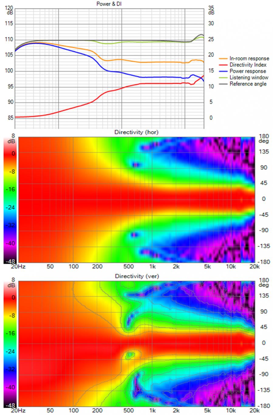
With a 600 mm WG and a 400 mm woofer, you get a 500mm CTC. The WG alone gradually widens starting at 1 khz and reaches 90 degrees at 250 Hz. The lower the XO, the better as the woofer is less directive; a stack of two of them would be better.
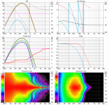
One could run an AXI2050 that low but then needs a 2" exit waveguide. While I was going through this thought process, discussion in ATH thread discouraged use of 2" exit due to HF beaming concerns. This brought up the question of how low an HF1440 could be used in a home environment. That obviously depends on how loud it is played:
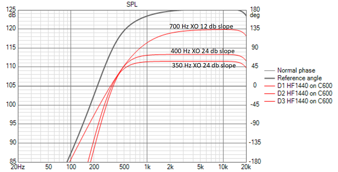
At my 80-95 db avg listening level, stress on the driver is well below what would exist with data sheet minimum XO of 700 Hz with 12 db slopes even at 350 hz XO.
With a 600 mm WG and a 400 mm woofer, you get a 500mm CTC. The WG alone gradually widens starting at 1 khz and reaches 90 degrees at 250 Hz. The lower the XO, the better as the woofer is less directive; a stack of two of them would be better.
One could run an AXI2050 that low but then needs a 2" exit waveguide. While I was going through this thought process, discussion in ATH thread discouraged use of 2" exit due to HF beaming concerns. This brought up the question of how low an HF1440 could be used in a home environment. That obviously depends on how loud it is played:
At my 80-95 db avg listening level, stress on the driver is well below what would exist with data sheet minimum XO of 700 Hz with 12 db slopes even at 350 hz XO.
Attachments

Hi, sorry I haven't followed the whole path you are taking so I'll ask did you ever consider using resistance enclosure (cardioid) instead of the quad side woofers? Looks like you are using 2nd order low pass for the side woofers, which seems to be the slope with resistance ports as well? Bass response might be a bit less, but the box could be smaller which seems to lessen diffraction effects if any concern about those. Cost would be you might have to add a sub. And I don't know if this kind of box can be simulated so some extra prototyping required.
Anyhow, been thinking about boxes lately and it looks like the smaller the better and trade-off being less volume so less bass from a driver. Making passive cardioid box(es) between about the schroeder frequency and the wave guide seems to me the most logical solution currently. Below about schroeder frequency bass boxes don't have to be that close to the "main" speaker which means less disturbance both sonically and visually since one could hide them into furniture 🙂 Would get the speaker closer to the corner as well. You only need to size each way (subs, cardioids and the waveguide) to support your SPL requirements and there probably is perfect size to have the reference level come out nicely.
edit. Thinking of it, a small bass box close enough to corner and resistance vents on top and bottom would be nice? Controls vertical directivity while horizontal is taken care by the room walls. Anyway, it is fun to follow what you end up with at the end and how close to simulations it eventually measures 🙂
My (its actually Kimmosto's) active cardioid emulates passive cardioid. The side woofers are driven out of phase with a DSP delay roughly equivalent to the sound originating from the back of the woofer cone. Level and delay are tuned to optimize the polar response; not a great deal of sensitivity there. The side woofers steal just a few liters of cabinet volume; not really noticeable in the long run. I'm only doing active because I lack the patience to develop passive and mistrust its repeatability, same mistrust of resistance vents.
If you want to fit tightly in a corner, you will do better with 2 12's stacked vertically than a single 15" woofer but if you are fitting tightly in a corner, you don't need cardioid bass. I want the freedom to roam away from room corners; I move too frequently. Also if you put equipment or TV on the front wall, sound from tight-in-corner speaker will reflect from it. Its nice to be able to pull the speakers out from the corner enough to clear the equipment without running into boundary interference.
With the waveguide I have, I'm not concerned about diffraction from the bass cabinet edges. A roundover would be nice but I don't think it would make much difference at the frequencies involved.
The rim drivers are more of a concern; I still have to ABEC them on the waveguide. Back a few months, I did a sim with fluid's help that showed the rim driver holes don't have much effect on the waveguide's polars. What remains to be seen is how much rim driver energy goes down into the waveguide and is reflected back from the CD's phase plug. With the 600 mm diameter WG, I wouldn't need rim drivers....
what about the rim drivers?
the waveguide has a length of 199 mm. The HF1440's phase plug is right at the exit so the round trip reflection path is twice that for a potential null frequency of 432 Hz. That is right on the edge of the initial pass band for the rim drivers, but I recently lowered the rim driver high pass to 350 Hz, which gave me less vertical narrowing at XO .
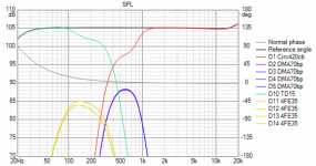
I have predictions of the bandpass driver's directivity from HornResp and Vituix Diffraction. From the latter:
radiation at angles more than 90 degrees off axis is about 10 db down. It can only create a ripple in the response, not a null. Furthermore, multiple drivers overlap in this range, allowing the ripple to be equalized.

Woofer and CD cross at 400 hz at about 10 db down. The rim drivers support the CD between 350 Hz and 800 Hz. It looks like the rim drivers are well below the CD in amplitude but that is deceiving. Each of the 4 rim drivers are plotted separately by Vituix, on top of each other. A single trace representing their sum would be 12 db higher. The support by the rim drivers makes it safe (and sound) to operate the HF1440 with such a low XO, in addition to the safety provided by not listening at PA levels.
(this doesn't mean I don't need to ABEC the rim drivers on the waveguide. It does mean I don't expect to find a problem when I finally get do that sim.)
the waveguide has a length of 199 mm. The HF1440's phase plug is right at the exit so the round trip reflection path is twice that for a potential null frequency of 432 Hz. That is right on the edge of the initial pass band for the rim drivers, but I recently lowered the rim driver high pass to 350 Hz, which gave me less vertical narrowing at XO .
I have predictions of the bandpass driver's directivity from HornResp and Vituix Diffraction. From the latter:
radiation at angles more than 90 degrees off axis is about 10 db down. It can only create a ripple in the response, not a null. Furthermore, multiple drivers overlap in this range, allowing the ripple to be equalized.
Woofer and CD cross at 400 hz at about 10 db down. The rim drivers support the CD between 350 Hz and 800 Hz. It looks like the rim drivers are well below the CD in amplitude but that is deceiving. Each of the 4 rim drivers are plotted separately by Vituix, on top of each other. A single trace representing their sum would be 12 db higher. The support by the rim drivers makes it safe (and sound) to operate the HF1440 with such a low XO, in addition to the safety provided by not listening at PA levels.
(this doesn't mean I don't need to ABEC the rim drivers on the waveguide. It does mean I don't expect to find a problem when I finally get do that sim.)
Attachments
Last edited:
- Home
- Loudspeakers
- Full Range
- Full range line array for wall or corner placement