I too would like to get away from rim drivers if possible but I also like smaller solutions.
I simulated larger waveguides with HF1440 and they work in simulation but with a caveat. Although the HF1440 is one of the best in this regard, the larger diaphragm drivers aren't as smooth up top as good 1" exit drivers and enter breakup at lower frequencies. In addition to that, the recent discussion and simulation of HOMs in the ATH thread calls into question simulation accuracy in that top half octave for the larger diameter throats. Then there is the cost and implementation difficulties for that larger waveguide. Not a problem for Fluid as he has his own CNC but an issue for me. OTOH, its not that hard nor exorbitantly expensive to get a 300 mm diameter waveguide printed.
And then when I looked closely, I found myself wanting a 300 hz XO for the large waveguide solution, which implies AXI2050 and a 2" throat with further risk to the high end.
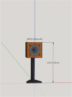
Consequently I went back to the 1" throat and serendipitously found the 3D cardioid which is hard to beat. The 300mm deep by 420 mm square package I have on the drawing boards now is very attractive to me, or will be once I come up with a stand for it. I believe I will be able to deal with any issue that arise with the rim drivers.
I simulated larger waveguides with HF1440 and they work in simulation but with a caveat. Although the HF1440 is one of the best in this regard, the larger diaphragm drivers aren't as smooth up top as good 1" exit drivers and enter breakup at lower frequencies. In addition to that, the recent discussion and simulation of HOMs in the ATH thread calls into question simulation accuracy in that top half octave for the larger diameter throats. Then there is the cost and implementation difficulties for that larger waveguide. Not a problem for Fluid as he has his own CNC but an issue for me. OTOH, its not that hard nor exorbitantly expensive to get a 300 mm diameter waveguide printed.
And then when I looked closely, I found myself wanting a 300 hz XO for the large waveguide solution, which implies AXI2050 and a 2" throat with further risk to the high end.
Consequently I went back to the 1" throat and serendipitously found the 3D cardioid which is hard to beat. The 300mm deep by 420 mm square package I have on the drawing boards now is very attractive to me, or will be once I come up with a stand for it. I believe I will be able to deal with any issue that arise with the rim drivers.
Given yesterday's discussion, I re-examined and revised my bandpass models. IF I stick with the relatively deep cone (compared to DMA series) drivers, I will need volume reduction plugs to push the bandpass peak out to 2 khz. Rounded over plywood disks easily CNCed suffice. Back in the day, I turned such a disk on a cheap lathe and got an 8" driver to work up to something like 1.4 khz. I had good correlation between HR and measurements for the bandpass ports in my synergy.
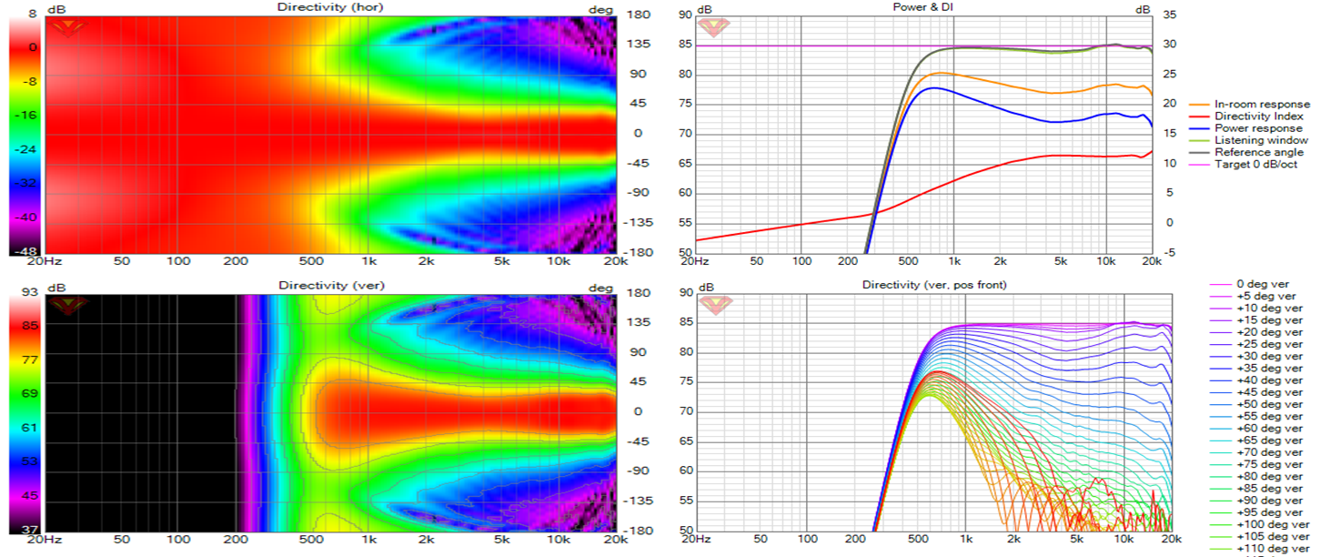
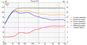
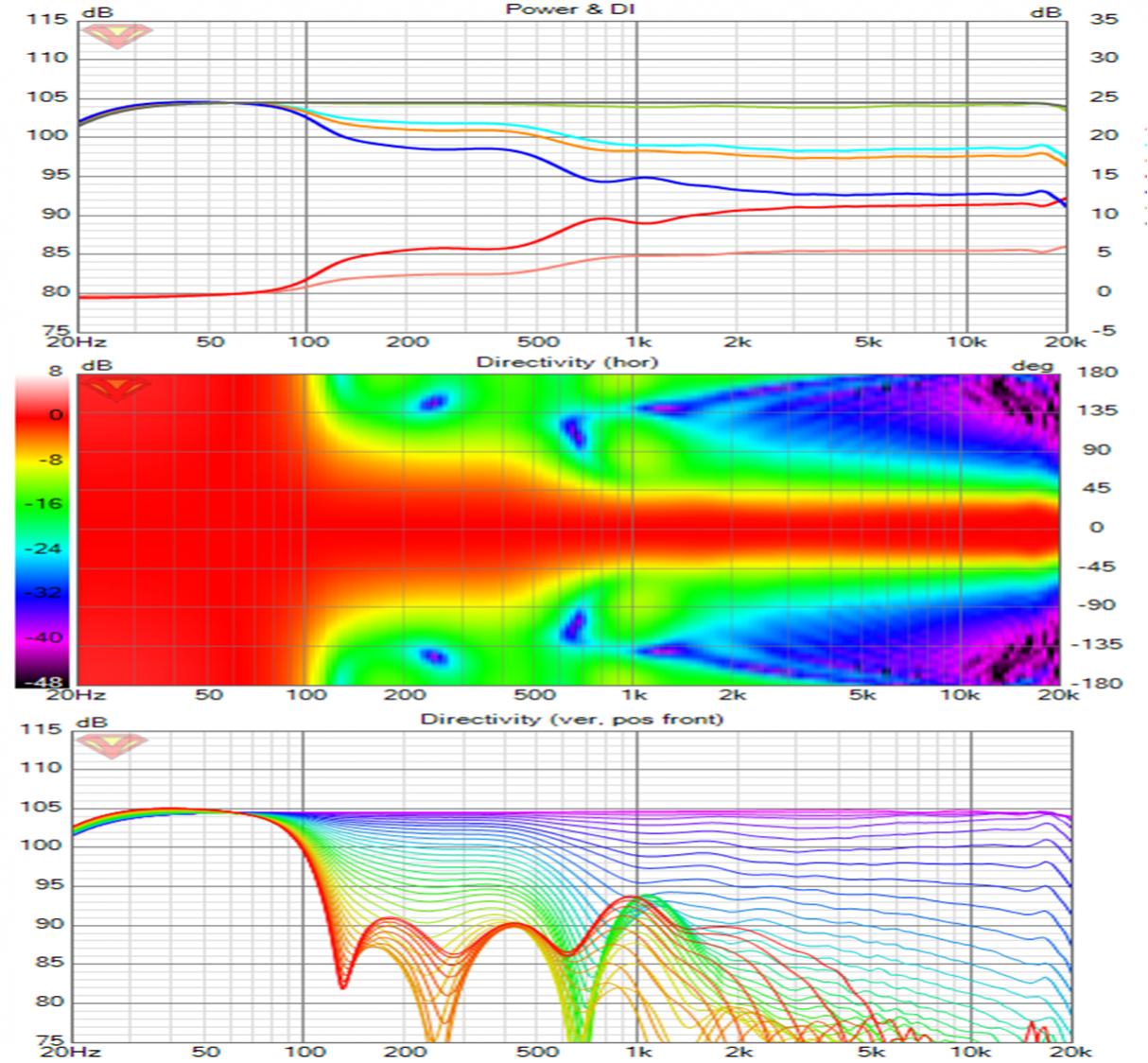
I redid the Vituix diffraction for the 5FE120BP as 4 drivers in a square instead of as a single driver. This different and likely (and hopefully) more accurate simulation improved my system simulation results - I was able to eliminate much of the ripple in the power response and DI and to do so with a 1 kHz XO!
I redid the Vituix diffraction for the 5FE120BP as 4 drivers in a square instead of as a single driver. This different and likely (and hopefully) more accurate simulation improved my system simulation results - I was able to eliminate much of the ripple in the power response and DI and to do so with a 1 kHz XO!
With that as preface, here is my current Vituix screenshot:
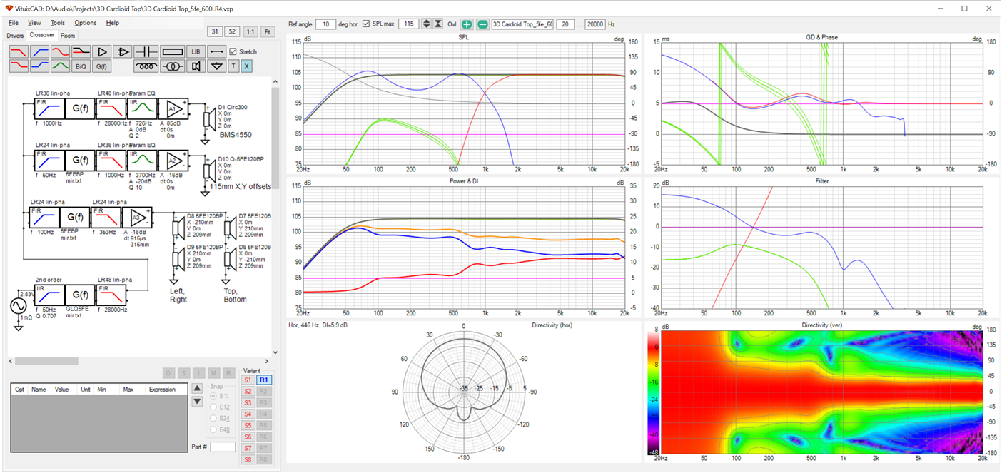
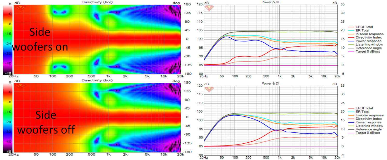
The improvements here are due to switching to the quad-5FE120 diffraction model and retuning the cardioid delay, amplitude and low pass filter cut off and slope for the side woofers. This tuning was done looking at the polar chart where the effects of changes are most visible. After that is was just a matter of choosing the XO frequency which meant going as high as I could before lobing from the rim drivers became visible.
In the central graphs, you will see three breakpoints in the DI, power response and PIR traces. The first one just under 100 Hz is the transition from monopole to cardioid response. The second and third , at near 500 Hz and 800 Hz respectively, bound the transition from the cardioids +/- 45 degree beamwidth to the waveguide's +/- 30 degree beamwidth. These directivity changes are inherent in the design. Looking at it now, I wonder if I can transition out of the cardioid pattern more gradually. I see that I can simply by lowering the cutoff frequency of the low pass filter in the side woofer chain. I'll leave that tuning for later while I finish this post.
Clearly this design hinges on the accuracy of the rim driver modelling. ABEC is the next logical step for that. If I wanted a really good speaker system (and didn't care so much about small) , I could probably get there more quickly by going the large waveguide route but I'm equally interested in innovating and the rim drivers are the closest I've come to that in a while so I will proceed in that direction.
Attachments
Impressively smooth!
You make a good point about 2" CDs - small disturbances at ~8kHz affect higher sibilants in a way that really catches my attention. 1" throats should be safe from this. I guess good 1.4" can be fine too, as defects above 10 kHz are that much less objectionable (to my ears), but the gain at the low end over the strongest of the 1" drivers is not that large. Round and round ...
Ken

I like the idea, form factor and the stand. I can't think that a DI like that is a good choice. If the polar looks good but the DI looks bad then I think something is amiss. There will always have to be a transition from the ~5dB of the Cardioid to whatever the waveguide ends up as, in a similar way to a big woofer transitioning to a waveguide. I wonder if the waveguide has too high of a DI at the top end loosing too soon at the bottom making a good transition a lot harder.and one more showing PIR
I realise getting the exact DI you want out of a waveguide is not super simple but it is now possible with Ath.
I've seen a lot of ATH generated horns with quite a flat DI curve. I've always wondered how one would combine that with the woofer underneath.
A few of the well regarded JBL examples seem to be modeled to have a more gradually rising DI curve (like the Revel Salon 2). To get that, the waveguide should show that rising trend as well, right? For instance, the JBL M2 shows a flatter DI from about 1800 Hz, but isn't the preferred one in the listeners preference tests of those two speakers.
Revel Salon 2:

JBL M2:

As most processing that is done here is adjustable, I'd personally aim for the rising gradual DI. It may require a slightly different waveguide.
These latest graphs are almost like a stepped ladder, and I think they would be hard to get pleasing sound (tonally) in a room because of that.
A few of the well regarded JBL examples seem to be modeled to have a more gradually rising DI curve (like the Revel Salon 2). To get that, the waveguide should show that rising trend as well, right? For instance, the JBL M2 shows a flatter DI from about 1800 Hz, but isn't the preferred one in the listeners preference tests of those two speakers.
Revel Salon 2:
JBL M2:
As most processing that is done here is adjustable, I'd personally aim for the rising gradual DI. It may require a slightly different waveguide.
These latest graphs are almost like a stepped ladder, and I think they would be hard to get pleasing sound (tonally) in a room because of that.
Attachments
Last edited:
I hear you.
I don't think there is anything terribly bad about the waveguide; its droop off axis around 6 khz has been noted but since that is well off axis, I don't think it will hurt the sound very much. Nevertheless, I've taken an AI to work on it.
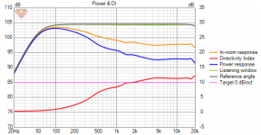
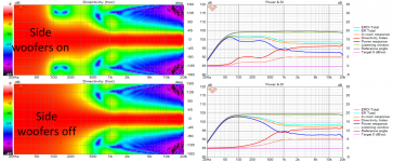
The major problem seems to be the transition out of cardioid. I tried to smooth it but apparently didn't try hard enough. Here is the response if I turn off the side woofers completely:

that suggests I should turn off the side woofers at a lower frequency (e.g 154 Hz instead of 275 hz). There may be occasions where I don't want/need cardioid. I could invert the drive to the side woofers, remove the delay, and augment the low end with them.
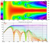
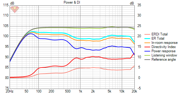
Now I have just one step in DI, at onset of cardioid, followed by a ramp to the waveguide's DI starting around 300 Hz. The WG's DI is higher than those of the salon and M2 by design because I'm anticipating smaller room. The Salon and M2 start to narrow around 10 khz; this doesn't happen with my WG until about 18 khz.
I don't think there is anything terribly bad about the waveguide; its droop off axis around 6 khz has been noted but since that is well off axis, I don't think it will hurt the sound very much. Nevertheless, I've taken an AI to work on it.
The major problem seems to be the transition out of cardioid. I tried to smooth it but apparently didn't try hard enough. Here is the response if I turn off the side woofers completely:
that suggests I should turn off the side woofers at a lower frequency (e.g 154 Hz instead of 275 hz). There may be occasions where I don't want/need cardioid. I could invert the drive to the side woofers, remove the delay, and augment the low end with them.
Now I have just one step in DI, at onset of cardioid, followed by a ramp to the waveguide's DI starting around 300 Hz. The WG's DI is higher than those of the salon and M2 by design because I'm anticipating smaller room. The Salon and M2 start to narrow around 10 khz; this doesn't happen with my WG until about 18 khz.
Attachments
Last edited:
A trustworthy source once said:
Horn Speakers - Is it me or....... | Page 7 | Audio Science Review (ASR) Forum
Floyd Toole said:In terms of sound quality, it seems that the constancy or smoothness of change in DI is more important than the DI itself. The dominant effect is spatial, not timbral. There is much discussion of this in forums, and personal preference is a factor.
Horn Speakers - Is it me or....... | Page 7 | Audio Science Review (ASR) Forum
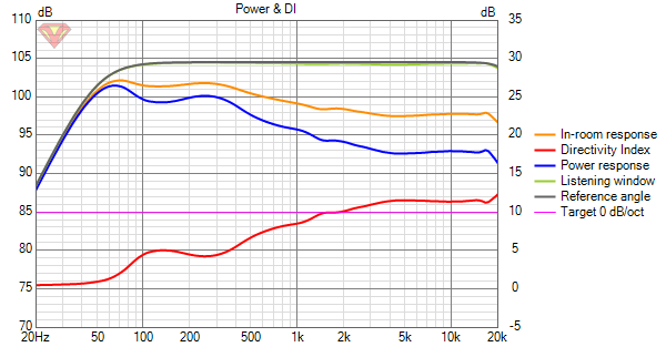
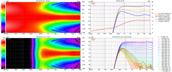
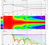
Changing the ATH rollback.startAt from .6 to .8 gets rid of the 4 khz droop in the waveguide response, but I'm left with 1db or so of Power response and DI ripple near the 1 khz XO.
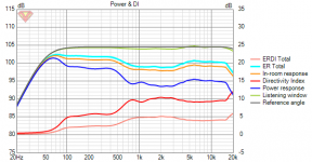
I've done what I could for the DI dip near 1 khz with 24 db slope on the CD and 48 db slope on the front woofers. Its incrementally better with a lower XO and lower slope on the CD but my synergy experience with BMS4550 suggests not going any lower.
I've done what I could for the DI dip near 1 khz with 24 db slope on the CD and 48 db slope on the front woofers. Its incrementally better with a lower XO and lower slope on the CD but my synergy experience with BMS4550 suggests not going any lower.
Attachments

I hear you.
I don't think there is anything terribly bad about the waveguide.
The WG's DI is higher than those of the salon and M2 by design because I'm anticipating smaller room. The Salon and M2 start to narrow around 10 khz; this doesn't happen with my WG until about 18 khz.
I'm not saying that there is anything bad about it but the shape and level of the DI curve are making it harder to integrate with the rest of the drivers.
My thinking is the DI should either be as flat as possible as low as possible or it should gently rise from the bottom to the top and any changes should be as smooth as possible.
Your waveguide is already narrow early on so the top end rise doesn't happen till later but if you compare the DI's they are becoming equivalent in the 15 to 18K range.
With Ath when trying to get the response smoother across all angles the DI tends to rise. The same thing happens with bmc0's generator script. If you target a flat DI there seems to always be some ripple in the on axis. Smoothing it out creates a rising DI. I can't shake the feeling that smooth everywhere has got to be better but Earl says the flat DI is more important.
I don't think its that hard to integrate the drivers; its more whether the integration results in a desirable system response.
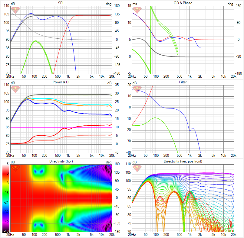
I have a very good XO between the waveguide and rim drivers at 1 khz. Its marred only by a 1 db dip in the power response at XO , with off axis lobes due to CTC with the rim drivers just beginning to appear. That power response dip is much less than what one gets with textbook XOs and conventional multiways.
Now would have been a good time for a dynamic gif showing how response above 400 Hz or so is identical whether there is a monopole woofer or cardioid woofer. In monopole mode, you get the smoothly rising DI, except for that small peak at XO and then flat until narrowing at the very top. But without the cardioid response insulating the response from nearby boundaries, that DI is likely to look very different in-room.
It took me a while to see it but the power response dip/DI peak is coincident with some very slight waist banding in the waveguide there. That is what makes it so hard to tune away.
It occurred to me that a 90 degree waveguide would be a better match to the cardioid woofers so I ran a few cases just changing the beam width. Unfortunately, these all needed more ATH work. One thing that stood out in all of them was that power response DIP. Here, for example, is for an 80 deg waveguide:
Things I am questioning now:
*** Is that 60 degree beam width a good thing? Authorities like Tom Danley recommend bigger waveguides with narrower beams for smaller rooms. Others point to wall reflections providing spaciousness and envelopment, if sufficiently delayed. But wall reflections won't be sufficiently delayed in the rooms I am targeting.
*** Is cardioid response a good thing given that it compromises the DI somewhat at and below the higher Schroeder limit of a small small room? I don't believe so and so I tend to ignore its effect on the DI when evaluating the response. I'm more worried about boundary interference.
Attachments
I figured there ought to be a way to use the side woofer's displacement below 100 Hz instead of simply high passing them to avoid fighting with the front woofers. There is a way but it requires another amp+DSP channel:

Here is the response:
Here is the response:
Attachments
You spend so much time controlling that horizontal dispersion, it always sort of makes me think/wonder about bushmeister's comparison:
Comparison of 'Xbush Sphere synergy horn', versus 'Balls of Prestige'.
In the end, he preferred (as well as his family) the wider dispersion of the more traditional speaker. Which still makes me wonder if your quest is a valid one.
Just something to think about... At least, for me it was 😉. I might have mentioned it before, but cannot get it out of my mind.
Last edited:
Thanks for that link. It was an interesting re-read. I found one tongue in cheek post by me in it offering my synergies for sale. But the comparison itself was flawed. It compared directive vs non-directive speakers in a well treated room. What would be the preference in an untreated room? I'm designing a speaker for a minimally treated room.
It seems I have two choices within my general approach: 90 degree waveguide + room treatment vs narrower waveguide plus ambience speakers. I'm with you and a surprising number of others in the latter camp.
I think a 90 degrees is too wide vertically, even if floor and ceiling combing are completely inaudible. I heard Gedlee speakers require ceiling treatment because of this. A 90V pattern sprays sound directly at floor and ceiling; there is no measurement distance that escapes floor and ceiling reflection. With 60V speakers in room, at 2m floor and ceiling reflections bypass the mic so there is some hope of getting decent resolution measurements in room.
I have some concern that 60H is too narrow. Its certainly wide enough from a coverage angle point of view. Toed in 30 degrees, a 60H speaker covers an entire room past some minimum distance related to L-R separation. With cardioid, the speaker isn't tied to a corner and can be aimed as needed. But 60H is too narrow for spaciousness and envelopment to be perceived without use of ambience speakers. I'm OK with that; that has been my intention all along.
I'm designing a speaker for a minimally treated room.
Duly noted, and all the more reason to keep an eye on that DI, I suppose. I'd want the DI to be as smooth as possible in an untreated room. Even though there's some leverage available with separately controlled ambient speakers.
You're playing with free standing speakers this time though, that gives you some extra options. I never regretted to have free standing arrays, as I've played with toe-in extensively.
(Later to be proven by running the sims; that what I found to sound good had good solid reasons behind it)
I'd try to manage the floor/ceiling and allow more freedom in the horizontal to improve the DI overall. At least, that's what I'd try and see if it works. Horizontal dispersion has the biggest influence on DI, and most probably on what we perceive. Else most 3 or 4 ways would stand no chance to sound decent. Many of them have sub-optimal verticals...
Sometimes these things end up being a semantics discussion. The point I am trying to make is that the peak and dip combination in the DI says to me that the two sides don't want to meet in the middle. The rim drivers are gaining too much directivity and the waveguide is losing too much at the crossover point.I don't think its that hard to integrate the drivers; its more whether the integration results in a desirable system response.
I have a very good XO between the waveguide and rim drivers at 1 khz. Its marred only by a 1 db dip in the power response at XO
As you say there are much worse examples in many speakers. I would rather remove those issues if possible and something else isn't lost in doing it.
That is a strange bridge between two positive amp channels and no ground path.I figured there ought to be a way to use the side woofer's displacement below 100 Hz instead of simply high passing them to avoid fighting with the front woofers. There is a way but it requires another amp+DSP channel:
re' semantics: I sometimes have trouble understanding what you are getting at.
I understand that the directivity match isn't perfect but OTOH its not off by much. A 1 db peak in the axial is all it takes to fill that dip at 735 Hz in the power response. If I compare it to JBL M2 or Revel Salon I see my power and axial responses are smoother than theirs (which to some extent is expected since mine is a sim) but also that the peaks/dips I would have to put into the axial response to smooth the power response would not be as large as theirs. At a higher level, the primary difference is the higher directivity of my system. The bass is more highly directive because of cardioid; the upper mid and treble by intent via waveguide design.
The real question to me seems to be whether that higher directivity is a mistake. The reviews don't help because they weren't done in as small a room as I will be using and they don't address whether ambient drivers will adequately compensate the higher directivity. By all reports it does provide the otherwise missing reflections needed for spaciousness and envelopment.
I don't know if high directivity will affect the sound stage; I suppose it will. That is a concern. I may have to develop a 90 degree waveguide that fits in the same baffle and try both.
re' the rim drivers are gaining too much directivity...
that is the manifestation of what CTC issue remains with the use of rim drivers. I can't raise XO higher to where the WG is narrower because rim driver beam is narrowing and lobes are starting to appear - unless I put the rim driver port in the waveguide rollback, which risks compromise due to rim driver sound entering the waveguide and being reflected back from the throat. Scaling the waveguide doesn't help; the problem scales with it.
The return for one amp is through the very low output impedance of the other. Its a way to sum two signal processing chains. I could do it just as well with the mixer in my sound card or back in the DSP engine but I can't model that in Vituix.
- Home
- Loudspeakers
- Full Range
- Full range line array for wall or corner placement