I ran one more case of the round over waveguide, continuing back in a cylinder to enclose the mid drivers, and then finally in this case, terminating in a baffle.
These look pretty much the same as in the earlier post so I'm satisfied there is no issue with bringing the waveguide+cylinder close to the woofer baffle.
These look pretty much the same as in the earlier post so I'm satisfied there is no issue with bringing the waveguide+cylinder close to the woofer baffle.
Attachments


Looking at a larger waveguide opened up that can of worms about the HF performance of a waveguide vs its throat diameter, that is being looked at in the ATH thread. And going larger is the wrong direction, so let's look at a smaller waveguide, one with a 1" diameter throat.
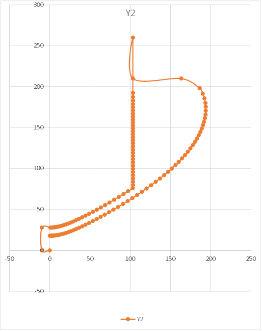
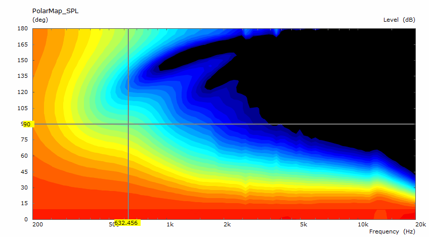
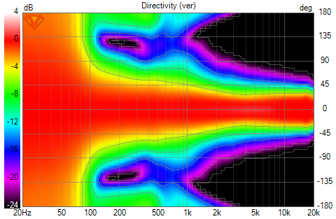
I used ATH to create a 300 mm diameter axisymmetric waveguide and liked the very first result that popped up
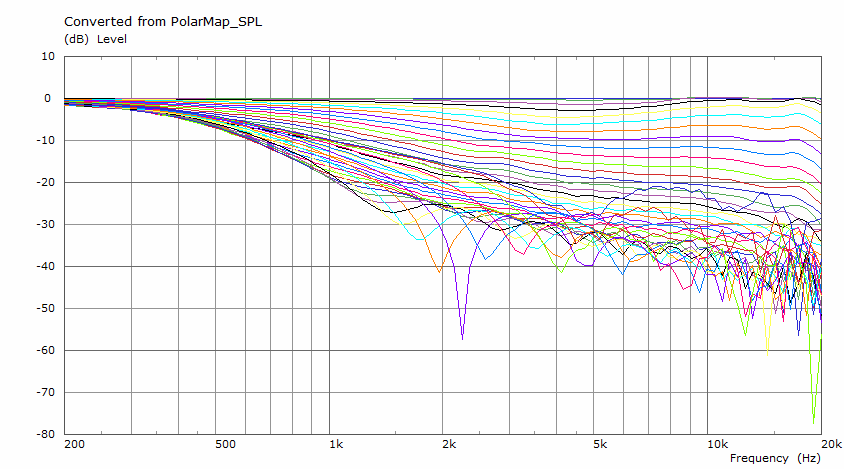
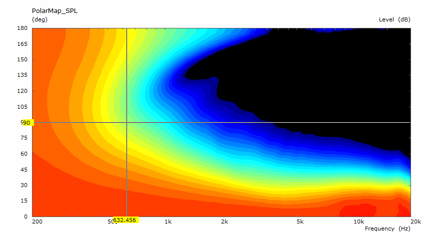
The benefit of the smaller CD exit diameter is immediately obvious: very little narrowing of pattern at HF.
Note that the pattern starts widening from +/- 30 degrees very gradually at about 2 khz but doesn't exceed +/-45 degrees until about 500 Hz.
Now, how to use this in a system. That is always the question!
I used ATH to create a 300 mm diameter axisymmetric waveguide and liked the very first result that popped up
The benefit of the smaller CD exit diameter is immediately obvious: very little narrowing of pattern at HF.
Note that the pattern starts widening from +/- 30 degrees very gradually at about 2 khz but doesn't exceed +/-45 degrees until about 500 Hz.
Now, how to use this in a system. That is always the question!
Attachments

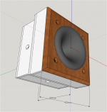
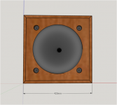
What I tried to do was to get cardioid-like response in 3 dimensions by putting side woofers on all 4 sides of the enclosure:
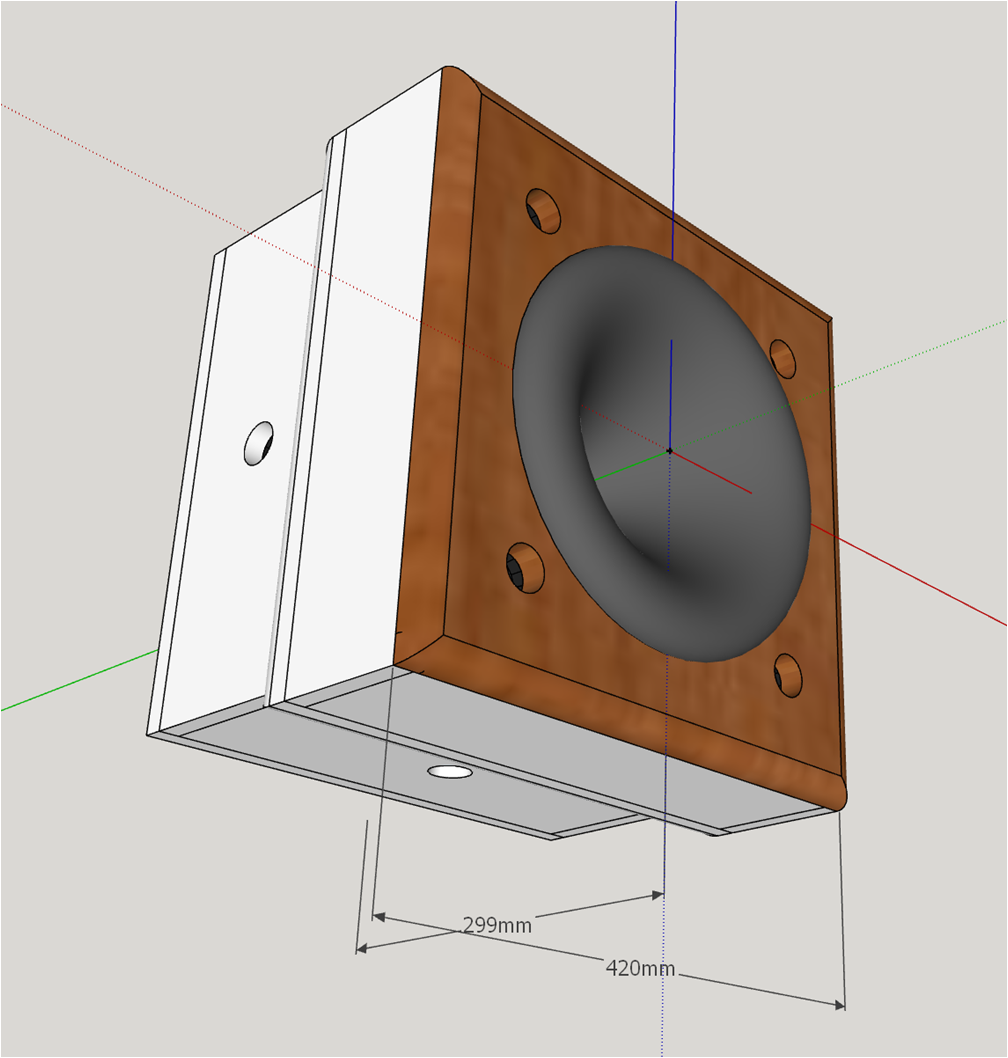
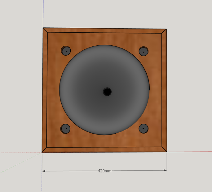
By lucky accident/mistake, front woofers moved away from the waveguide rim. That worked so well, I kept them there.
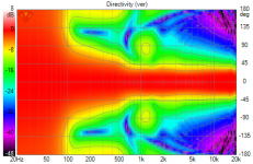
Directivity is very smooth and controlled with a gradually widening pattern below about 600 Hz.
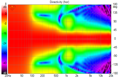

although Vituix displayed them differently, V and H patterns are the same as you would expect from the symmetry.
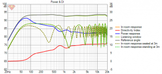
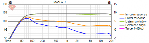
Crossover frequency in range of 900-1100 Hz and slope affect not only directivity but also power response and DI. In optimizing directivity, I see I've ended up with larger ripples in power response and DI than I like so this certainly isn't the last XO.
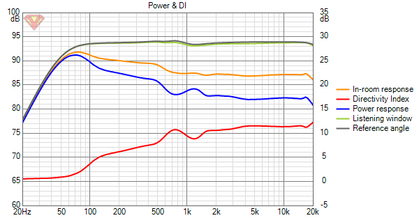
Finally I have a design that won't break my back. The one drawback to it is it does have a floor bounce null. OTOH, its got the best standing height response I've seen!
Reference angle and listening window curves in the above graph are for standing height.
By lucky accident/mistake, front woofers moved away from the waveguide rim. That worked so well, I kept them there.
Directivity is very smooth and controlled with a gradually widening pattern below about 600 Hz.
although Vituix displayed them differently, V and H patterns are the same as you would expect from the symmetry.
Crossover frequency in range of 900-1100 Hz and slope affect not only directivity but also power response and DI. In optimizing directivity, I see I've ended up with larger ripples in power response and DI than I like so this certainly isn't the last XO.
Finally I have a design that won't break my back. The one drawback to it is it does have a floor bounce null. OTOH, its got the best standing height response I've seen!
Reference angle and listening window curves in the above graph are for standing height.
Attachments
-
 3D CardTopPerspective.png370.4 KB · Views: 274
 -
 3D CardTopFront.png149.8 KB · Views: 289
 -
 3D Cardioid Top_5fe Directivity (ver).png150.3 KB · Views: 269
 -
 3D Cardioid Top_5fe Directivity (hor).png145.8 KB · Views: 284
 -
 3D Cardioid Top_5fe Power+DI.png28.5 KB · Views: 272
 -
 3D Cardioid Top_5fe Power+DI_standing.png46.5 KB · Views: 286
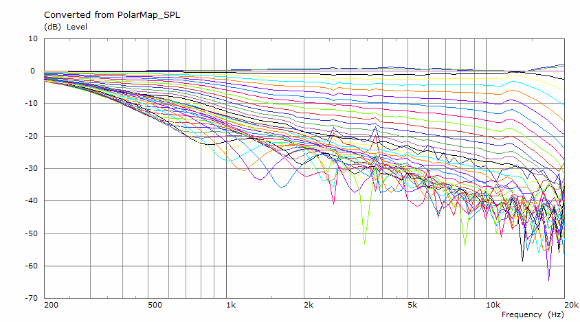
Shame about the depression between 2 and 8K, you should be able to get rid of that and have it look more like the one above in that region.I used ATH to create a 300 mm diameter axisymmetric waveguide and liked the very first result that popped up
Interesting layout, it's always annoying when you get a smooth polar a funky DI. I've been considering a 12" and 1" combination myself.Crossover frequency in range of 900-1100 Hz and slope affect not only directivity but also power response and DI. In optimizing directivity, I see I've ended up with larger ripples in power response and DI than I like so this certainly isn't the last XO.
I've never been able to run a full 3D simulation with rolled back waveguides using only an external subdomain. The interface was always difficult to get right, when really it shouldn't have such an effect making it difficult to compare against the circsym options.
I wonder if having the rollback end on a flat baffle is better than just having the curve meet the baffle as smoothly as it can.
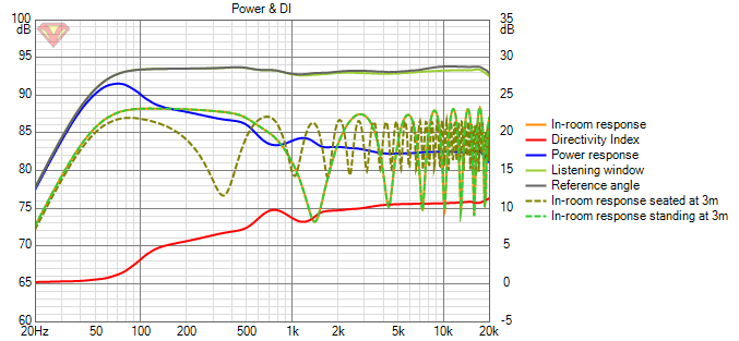
I think the depression between 2 and 8 khz was in the last graph, which was showing response for standing height. It goes away when I lower the mic. At seated height it isn't there, just +/- 0.4db peak before and depression after 1 khz that I inserted in reference angle response to make PIR and power response look better.
So far, the best simulation has come from using a larger (large enough to get the same pattern control without rim drivers) 1" throat waveguide and assuming it has been synergized. That ignores the effect of the mid-woofer ports on the pattern but gives nicely smooth power response and DI. I'm having very little luck reducing the DI peak of the rim driver system near 770 Hz but the corresponding dip in the PIR is very small so I wonder if it matters.
I have greater trouble with full 3D simulation than you because I'm still struggling with Fusion360, although making progress. Modifying the nodes file helps in the meantime. That trick should work for modelling a roundover smoothly blending into the baffle, albeit a round one. My impression from the few cases I've run is that it almost doesn't matter what is behind the waveguide if it has a full 180 degree round over.
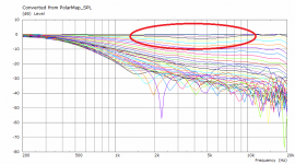
I was talking about the ABEC sim circled here, the previous ABEC graph with a bigger waveguide didn't show that tendency.I think the depression between 2 and 8 khz was in the last graph, which was showing response for standing height. It goes away when I lower the mic.
Some of mabat's earlier simulations showed differences, the rollback is definitely more tolerant of close surfaces but I don't know if the baffle right at the rollback junction violates that in any way.My impression from the few cases I've run is that it almost doesn't matter what is behind the waveguide if it has a full 180 degree round over.
Attachments
why I think rim drivers are rarely used and probably a bad idea
Still watching with great interest. I've continued to ponder on the remark I made several weeks ago, about the trouble I had with ports for rim drivers with ports. I realize now why that's a completely different ballgame from MEH ports which we've seen work well. There are probably more than the two reasons I give below why rim-mid-ports are much harder to get right, but these two led to most of the problems that showed in my measurements.
1) the ports in the MEH, if at the correct point on the expansion for their pass band, are strongly damped by the resistance of the horn (they are loaded by the horn) -much more so than any practical damping material that could be put into the port. This can be seen in simulations of MEH responses. Conversely, rim driver ports are almost in free space, so there's considerably less damping, and therefore the ports have high Q resonances. Eyeballing from your rendering: with ports roughly half the area of yours but otherwise a similar arrangement, I saw Q>10 at the Helmholtz resonance (a bit below 2 kHz for me, IIRC).
2) with Q>10 and small dimensions, the ports need to be accurately matched if their response is to be equal. With rim drivers, any mismatch will lead to really annoying off-axis response errors where one port dominates in a narrow band of frequency, and another dominates at a slightly different frequency. This can only be corrected by having separate amplifiers and filters for each port. In the MEH this problem is diluted by the factor explained above (much lower Q) and because the ports blend in the horn - as can be seen in tests where 1, 2 or 4 ports are used with little change in directivity (if any). Try that with rim drivers.
I suspect that rim drivers might bring problems that are very hard to solve. Now I believe that my failure to make them work was almost inevitable. It's a long time since I used Hornresp, but I believe you can simulate a single rim driver, rear chamber and port, and vary the dimensions by small amounts to find the difference in the response.
In your design there's nearly enough space to bring the rim drivers out to the front panel, which would reduce response variation down to that of the drivers (the variation I see in my 3FE25s is small, but still shows up in off-axis measurements and I'm definitely not going to split the drive to four of those).
Ken
Last edited:
^^if i remember this kind of feature in ATH response was due to the depth parameter being off from optimal.
nc535, I think the DI/Power ripple can be adjusted smoother by adjusting the xo frequencies, slopes and delay (on the mids), look at the phase plot for cues what to adjust. At least this is the process how I got smoother results over the xo region.
nc535, I think the DI/Power ripple can be adjusted smoother by adjusting the xo frequencies, slopes and delay (on the mids), look at the phase plot for cues what to adjust. At least this is the process how I got smoother results over the xo region.
A lower crossover (600LR4) seems to be the cure for the 770 Hz ripples in the power response and DI:

but at what price? I'm not ready to Synergize the waveguide; I wonder if an adapter to an HF1440 would do the trick? I'm pretty sure BMS4550 can't be pushed that low.
but at what price? I'm not ready to Synergize the waveguide; I wonder if an adapter to an HF1440 would do the trick? I'm pretty sure BMS4550 can't be pushed that low.
Attachments

In your design there's nearly enough space to bring the rim drivers out to the front panel, which would reduce response variation down to that of the drivers (the variation I see in my 3FE25s is small, but still shows up in off-axis measurements and I'm definitely not going to split the drive to four of those).
Ken
I have been worried about rim drivers actually in the waveguide or, more precisely at the maxZ point on the rollback, so I've been looking for solutions that wouldn't require as much experimentation.
You bring up points I hadn't considered but when I did an abec of rim drivers on a different waveguide some time back those problems didn't show up. It seemed the rim ports and chambers were innocuous; perhaps because their fraction of the WG circumference at their center was small; perhaps because of simulation limitations.
Did you post any of your work with rim drivers?
In this design the rim drivers are brought out to the front panel. They are indeed large, which is to support response well below 100 Hz without issue due to particle velocity. With a higher low end response requirement, they could indeed be smaller.
In their current positions, their use is reminiscent of BWaslo's use of a woofer edging out from behind his 3D printed waveguide to extend pattern control as much as it is rim drivers.
Small Syns
Bwaslo deserves credit for the idea and I look at his work as a limited proof of concept.
I was talking about the ABEC sim circled here, the previous ABEC graph with a bigger waveguide didn't show that tendency.
Some of mabat's earlier simulations showed differences, the rollback is definitely more tolerant of close surfaces but I don't know if the baffle right at the rollback junction violates that in any way.
If I could get mabat to run my cfg file through his optimizer, I bet that droop would go away!
Unfortunately, I've lost the measurements from the array with ports - I'd also forgotten that was with Peerless drivers not the 3FE25.
I must have missed ABEC results that with the Helmholtz resonance. I would expect to have seen a pronounced peak at the top of the pass-band of the port, before the 2nd order roll-off.
It might be worth mocking up a test baffle - a hole of about the right size in a baffle at big enough to get the edges out of the way. I did that and saw the resonance, but decided to continue (a mistake).
ps. there's been much to learn from your analyses - apologies that I'm commenting negatively, there's much that's positive!
Ken
Oh is the port response what you show in Full range line array for wall or corner placement (blue curves)? I had missed that, I'm surprised the Q is only ~2 and unsure whether it's the raw response of the port or not,
Last edited:
s.
Did you post any of your work with rim drivers?
egg on my face for not remembering your (Kstrain) thread after all the times I posted in it. I've had my head down in this for too long.
After a decade of planning, thanks to forum members
- but I don't see much relevance of that thread to rim drivers - except for the driver matching requirement which I will now be alert to. Thank you.
I spent a bunch of time simulating arrays of various kinds but concluded that a good waveguide was a better solution than rings of drivers. That conclusion was strengthened when I combined cardioid with waveguide as in my latest effort here.
Having cardioid response below the waveguide eliminates the need to be thin and hug the wall. You could also say that if the box is thin enough, it doesn't need a cardioid response.
No egg! I was a too sparing of information early in that thread (the Mk I) - it really was meant as a "thank you" to the people I mention and a starting point for others who might want to explore the same territory.
If you plan to put drivers behind cut-outs or ports, even the side drivers for cardioid, it would be great to see the results from a test baffle with one port. I wish I'd kept mine, but I had no thought of posting about the arrays until long after those measurements. It may be that your approach works out differently due to the choice of low-pass frequency, etc.
As you know from your extensive simulations, it's hard to get an array to work with a central waveguide (or anything other than a smaller array) and the combination of that and port resonances that were different for all six members of the ring in my "Mk I" array is what made me give up that idea.
The (active) cardioid plus waveguide idea is a good one. A good-size waveguide and cardioid should be able to be made nearly ideal for horizontal off-axis response. What's stopped me trying it beyond simulation is that my room is more tolerant of <1kHz off-axis horizontal than vertical. When I look at an ungated impulse, it's all relatively innocuous apart from floor and ceiling bounce. I'm doubtful that cardioid would help much for the effort. I keep wondering about making side-boxes with pairs of 3FE25s to sit adjacent to my Harpers, to explore the difference.
Ken
There is nothing like a line array for neutralizing floor and ceiling reflections!. A waveguide can't do as well, certainly not an axisymmetric one and if not that than pattern flip. I couldn't go narrower than +/-30 degrees in the vertical without getting too narrow in the horizontal. But even at +/-20 degrees V, as distance increases you will eventually encounter a floor null.
So what I hope to do is reduce the lowest floor response null and hope/expect that the upper midrange combing with floor and ceiling reflections will be inaudible due to BSP (brain signal processing) and ambient sound field filling in the nulls.
I imagine your tall arrays can approach line array like vertical performance.
I have done bandpass ported test baffles in the past, I doubt if I still have or can find their measurements...
What helps with my current set of ports is that the bandpass peak is well outside the passband, - around 2khz for a sub 1khz low pass with a steep FIF fiter, which will minimize matching difficulties.
Agreed on all points. BSP is important, and perhaps especially effective for floor and ceiling reflections.
As you have an octave to spare, and are using steep filters, you can probably neglect the Helmhotz resonances, even if Q~10 they should be far enough down not to matter. I thought the resonance might be lower - you've probably got less volume between the cone and the port than I had guessed.
Ken
As you have an octave to spare, and are using steep filters, you can probably neglect the Helmhotz resonances, even if Q~10 they should be far enough down not to matter. I thought the resonance might be lower - you've probably got less volume between the cone and the port than I had guessed.
Ken
1) the ports in the MEH, if at the correct point on the expansion for their pass band, are strongly damped by the resistance of the horn (they are loaded by the horn) -much more so than any practical damping material that could be put into the port. This can be seen in simulations of MEH responses.
This is something that Tom Danley mentioned in an ASR thread on his new speakers recently when there was a discussion about the general bandpass peak. I suspect that this could be simulated in ABEC but because all of the port surfaces and driver membranes are considered as solid boundaries (unless they are given specific damping values) the diffraction from those swamps everything out.
Using a lumped element model for the bandpass port should help clear up the diffraction and show the resistance effect better. Not really applicable to Jack as he is trying to move them out further.
Thanks Fluid, looked at ASR and it has changed a lot since I last looked, with all the speaker tests to catch up with; and reading TD is always valuable.
With steep FIR filtering and an octave to spare, Jack doesn't need to worry about the ports. That spare octave is a key aspect of the design. I didn't have a gap like that t work with, and that's what led to all my trouble with ports. Previous MEH experience had falsely taught me that ports are not very critical, true in an MEH, false otherwise.
Ken
Last edited:
I'd be curious about the solution with a driver like the HF1440, on a bigger waveguide made to suit this driver.
What's not to like if one can forgo the rim drivers completely? I'd guess the HF1440 can extend low enough to make it possible.
https://faitalpro.com/en/products/HF_Drivers/product_details/datasheet.php?id=502020185
** at least for a Home Audio solution **
What's not to like if one can forgo the rim drivers completely? I'd guess the HF1440 can extend low enough to make it possible.
https://faitalpro.com/en/products/HF_Drivers/product_details/datasheet.php?id=502020185
** at least for a Home Audio solution **
That was my thinking I hope I will find out at some point 🙂I'd be curious about the solution with a driver like the HF1440, on a bigger waveguide made to suit this driver.
What's not to like if one can forgo the rim drivers completely? I'd guess the HF1440 can extend low enough to make it possible.
Attachments
Last edited:
- Home
- Loudspeakers
- Full Range
- Full range line array for wall or corner placement