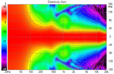
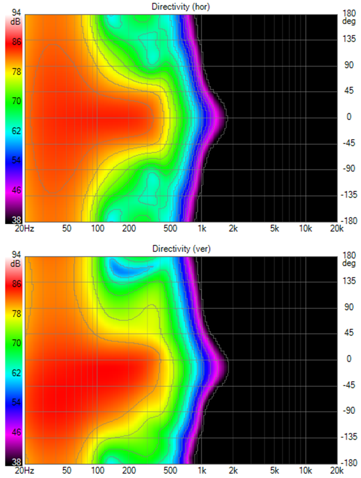
In all honesty, I like the above result (horizontally) better than the second graph showing nulls at the side. The graph right above shows a nice pattern control with even and smooth behavior even further off axis. Which is the energy that would lite up the room.
Horizontally I think nulls at certain parts of the frequency curve could create an unbalance in room sound. More so in the horizontal plane than vertically I would think.
As these are suggestions/sims for free standing I'm a bit surprised how far you intent to use beam steering horizontally. I know/realize I use absorption to get much of the same effect, but I do wonder how wide the ideal pattern should be for a free standing speaker. In other words, it's awesome that you can steer it by that much, the question really is: should you?
That is a very good question...and the answer is it depends. If the main beam is too narrow, then I might need to add ambience speakers. Who do we know that has done that?
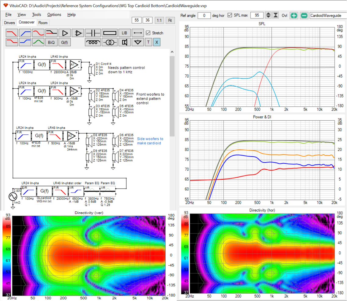
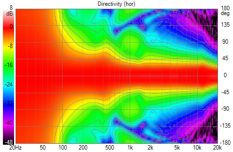
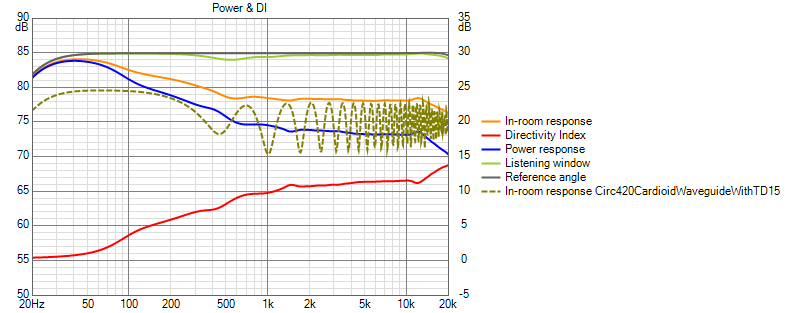
I agree that the graph right above has very attractive polar maps (that is what I was excited about yesterday PM but I forgot to press the final button to post it until this morning) and that the cardioid gives impressive pattern control. I did not perceive the cardioid's side nulls below 1 Khz to be problematic, although they might account for the small dip in the power response in the 500 Hz to 1 Khz octave. Even the sim you liked has horizontal nulls to the sides above 1 khz. In fact both sims are pretty much the same above 1 khz, which is to be expected as they use the same waveguide.
As to beam width, I'm between a rock and a hard place. Axisymmetric waveguides have proven superior in these simulations because the rectangular/elliptical shapes lose vertical pattern control too soon. With axisymmetric WG, you get the same pattern for both V and H, which isn't optimal, at least not for a large room. In a large room, you want a wide H and a narrow V. The H reflections will have a long delay and contribute positively to the sound. In a small room, the H reflections would be too early so you go for a narrower pattern. That is the "it depends".
I think for a large room, I would go in the Perlisten direction to get a wide H beam. Anyone that can afford that class speaker likely has a large room to put them in. These speakers, OTOH, are destined for a small room with WAF restricted treatment.
... back to the 60 degree waveguide. I think 60 degrees is a good compromise between H and V pattern control requirements. (Narrower V would be better, if achievable) I think the side nulls below 500 Hz you get with cardioid are more beneficial in reducing near boundary effects than harmful in reducing reflections needed for envelopment.
Last edited:
That is a very good question...and the answer is it depends. If the main beam is too narrow, then I might need to add ambience speakers. Who do we know that has done that?
Can't argue there... 🙂
I guess you're trying to create something that needs minimal help from room treatment? I can surely understand that. Even though I like the train of thought behind wide and even horizontal directivity, I could never make that work in my room. My listening corner is too asymmetric for that.
With side drivers you may even have some Beolab options 🙂. Having a wide and narrow 'option' wouldn't be a bad thing!
Still think there's merit in the patterns from the graph above. It would be even better if the 'islands' seen beside 1 KHZ would be at ~1850 Hz. Wouldn't hurt to have a little more (side) energy there.
Last edited:
did you notice those nulls were out past 90 degrees, meaning behind the plane of the speaker's baffle?
That's why I like this one:
The other one:
is where the nulls reach deeper (or more to possible wall/furniture)...
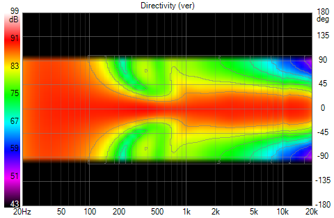
I specifically like the horizontal in the top picture...
The other one:
is where the nulls reach deeper (or more to possible wall/furniture)...
I specifically like the horizontal in the top picture...

The verticals aren't bad either:

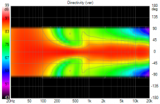
The vertical beam width is higher than I'd prefer in that it just moderates, doesn't prevent a floor null at 3m listening distance

The RECT400 WG I had been using is ~ 80H 40V (or was intended to be) . I couldn't make it a cardioid just by adding side woofers; will try again with different front woofer configuration...
The vertical beam width is higher than I'd prefer in that it just moderates, doesn't prevent a floor null at 3m listening distance
The RECT400 WG I had been using is ~ 80H 40V (or was intended to be) . I couldn't make it a cardioid just by adding side woofers; will try again with different front woofer configuration...
Attachments
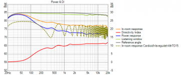
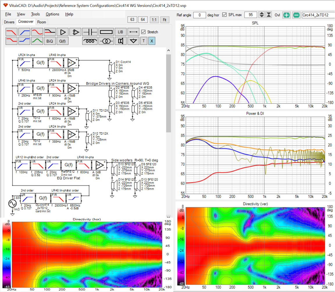
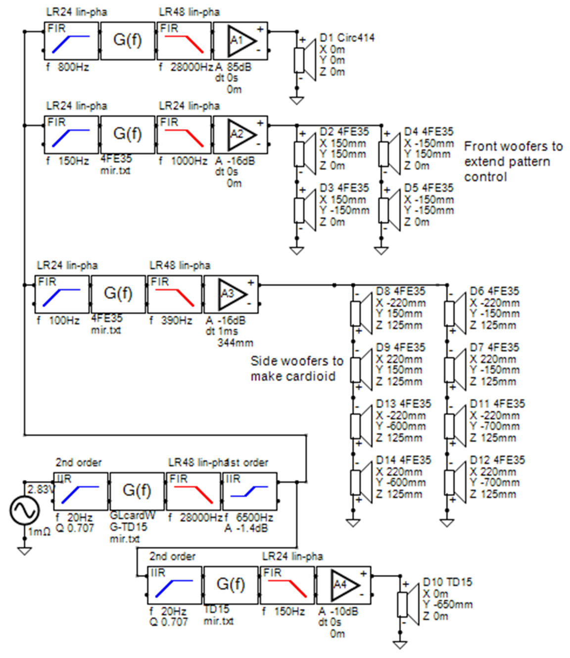
I like the (for me 🙂) relatively straightforward if not actually simple 4-way XO. It is 4 ways but each way just needs to be equalized flat. Delay for the cardioid is done via DSP delay rather than by IIR LPF. Both delay and filter cutoff frequency can be used to fine tune the directivity. The amount of overlap among waveguide, front woofers and floor woofers also tunes the directivity. There is a final global eq to adjust the axial response to target. After equalizing axial flat, I shelve down 1.4 db first order at 6500 Hz to flatten the high end of the PIR, predicted in room response.
Attachments
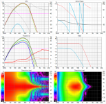
Another day, another iteration on the waveguide and the crossover. In this version, the WG plays 600 Hz up, so the exit has to be 1.4" for HF1440. The 4 front woofers play only 450 Hz to 1 Khz, so they can be as small as DMA45's, for 105db peak SPL. The 15" woofer is moved up off the floor a bit and plays up to 450 Hz, reducing the primary floor null.
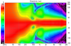
The far off axis nulls have been removed from the H Polar Map
The vertical polar map shows a narrowing at XO but remains tall enough for a good standing response

The PIR is flat without tilting axial except in the top half of the top octave. The power response and DI are as good as I've seen. It does narrow at HF, though. There is still a small floor reflection dip, much reduced from the prior version
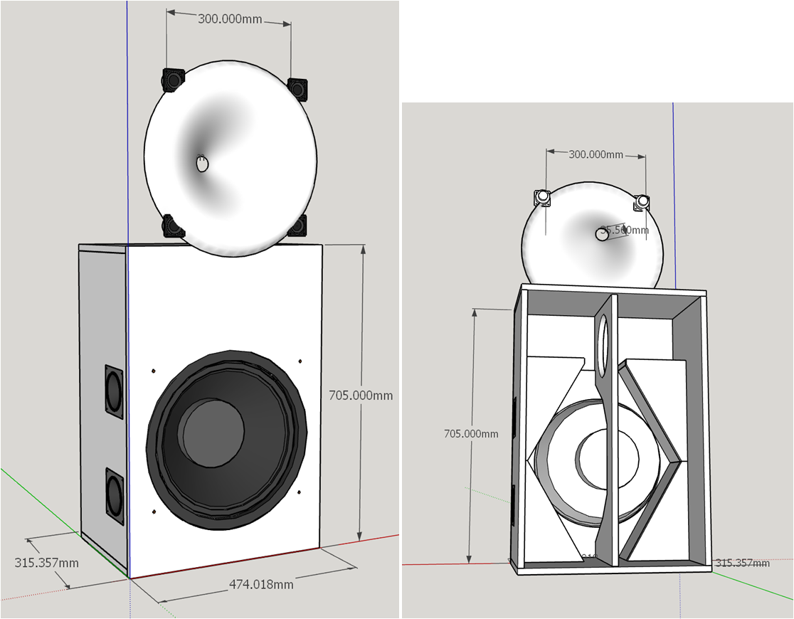
Finally, I have an idea what cardioid costs in terms of footprint. The box is only ~30mm than the corner box and only 315mm deep. It does not sit deeply in a corner though. The interior partitions to create sealed spaces for the 4" side woofers also brace the front baffle.
The waveguide will have a 180degree rollback, the bandpass front woofers will play through holes in the flattest part of that roll back, and (hopefully) the outside edge of the rollback will be outside the outside edges of the woofer....
The far off axis nulls have been removed from the H Polar Map
The vertical polar map shows a narrowing at XO but remains tall enough for a good standing response
The PIR is flat without tilting axial except in the top half of the top octave. The power response and DI are as good as I've seen. It does narrow at HF, though. There is still a small floor reflection dip, much reduced from the prior version
Finally, I have an idea what cardioid costs in terms of footprint. The box is only ~30mm than the corner box and only 315mm deep. It does not sit deeply in a corner though. The interior partitions to create sealed spaces for the 4" side woofers also brace the front baffle.
The waveguide will have a 180degree rollback, the bandpass front woofers will play through holes in the flattest part of that roll back, and (hopefully) the outside edge of the rollback will be outside the outside edges of the woofer....
Attachments

Have you tried without the DMA45's and the woofer and side drivers up under the horn. That's what I am thinking with a driver on the rear at floor height to provide some vertical spread.Another day, another iteration on the waveguide and the crossover. In this version, the WG plays 600 Hz up, so the exit has to be 1.4" for HF1440. The 4 front woofers play only 450 Hz to 1 Khz, so they can be as small as DMA45's, for 105db peak SPL. The 15" woofer is moved up off the floor a bit and plays up to 450 Hz, reducing the primary floor null.
I am trying to model this myself in Vituix but I am finding that I really don't understand how to work it very well so far 🙂
I've been around the loop several times. Big WG with big woofer needs bridge drivers to avoid narrowing at XO due to CTC. Current configuration is the best I've found. To answer your earlier rhetorical question - Yes, it's worth it!
Vertical narrowing?Big WG with big woofer needs bridge drivers to avoid narrowing at XO due to CTC.
Which question was that?To answer your earlier rhetorical question - Yes, it's worth it!
When I tried to model the cardioid woofer box I used the enclosure tool based on the TS specs to generate the 2pi response, fed that into the diffraction tool and placed the microphone at the centre of the driver and then used the XYZ and R to represent their real positions. Is this what you did? The low frequency box rolloff seems to disappear in the diffraction simulation step.
I called it narrowing at XO but better description for this example might be directivity mismatch
This is 12"W - HF1440wg - 12"W at 400mm CTC, crossed at 600 Hz
The question was whether rim slot woofers were worth it, first posed in your 2 way abec thread.
I generated directivity for the side woofer cardioid by using diffraction tool but got the 2 pi response by tracing the data sheets. I also equalized the drivers flat within their passbands using the mirror function of the calculator tool. I rely on separate simulations to ensure I'm not exceeding Xmax. This is the same thing I do for any driver for which I don't have a full set of polar measurements.
Re' low frequency box roll off disappearing- did you check "full space" box in diffraction tool?
I didn't spend any time with rear woofer cardioid. Small side woofers with single or dual front woofers fit my architecture much better.
Attachments
While I don't really like the horns being generated at the bottom of the waveguides response, the vertical is pretty consistent through a decent range and much better than most vertically separated systems. I don't know that I think making the vertical response wider in the 500 to 200Hz region is an improvement overall in the other graphs. A cardioid woofer below the horn seems to help and is much simpler which I like and could possibly be done passively or at least semi passively which appeals to me more these days.
Yep, I realised I must have not ticked the Full space button. I'm redoing the whole thing from scratch as it probably wasn't the only thing I stuffed up.
Could you show me a graph of the pattern of the cardioid side woofers just by themselves with everything else turned off?
Yep, I realised I must have not ticked the Full space button. I'm redoing the whole thing from scratch as it probably wasn't the only thing I stuffed up.
Could you show me a graph of the pattern of the cardioid side woofers just by themselves with everything else turned off?
Yes, that looks good; except for the lack of response below 100 Hz. I didn't want to give that up. Thus the high pass in the side woofers and given they are being high passed, they don't need to be large.
I agree and have said several times its a mistake to make the vertical response too wide in the 200 to 500 hz region, despite ideal of perfect directivity match. That leads to a floor null. The trick is to make it just wide enough to suit your target listening window or just narrow enough to limit the floor null.
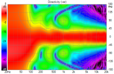
Here are my side woofers playing solo viewed from the front LP
I agree and have said several times its a mistake to make the vertical response too wide in the 200 to 500 hz region, despite ideal of perfect directivity match. That leads to a floor null. The trick is to make it just wide enough to suit your target listening window or just narrow enough to limit the floor null.
Here are my side woofers playing solo viewed from the front LP
Couldn't one use a bit of phase trickery that both woofers add up below 100 Hz?
I can understand the use of the rim drivers if it leads to a floor null at the crossover.
I can understand the use of the rim drivers if it leads to a floor null at the crossover.
Its matching the vertical directivity of the waveguide in that region that leads to a floor null. The rim driver minimizes CTC. You can then get the vertical directivity you want by choice crossover frequency and slope and overlap of the waveguide, rim drivers and front woofer. I deliverately narrowed the vertical window in the 300-500 Hz region to limit the floor null (post 1338) vs best directivity match (post 1328)
The side woofers allow you to have a cardioid response above 100 Hz while response to the front remains flat down to 20 Hz, or however far you equalize.
Here are polar maps of the front and side woofers playing without waveguide and rim drivers:
The side woofers allow you to have a cardioid response above 100 Hz while response to the front remains flat down to 20 Hz, or however far you equalize.
Here are polar maps of the front and side woofers playing without waveguide and rim drivers:
Attachments

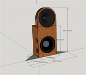
I played with the Sketchup drawing today.
There is only so much you can do aesthetically. I hid the rim driver holes (1cm) diameter in the waveguide roll back and gave the cabinet a round top.
There was room so I upgraded the rim drivers to DMA70, which have 3x the Sd of the DMA45. Will likely use the space behind the waveguide for the computer and amps needed to run it.

The grey triangle shows how it fits in a corner.
There is only so much you can do aesthetically. I hid the rim driver holes (1cm) diameter in the waveguide roll back and gave the cabinet a round top.
There was room so I upgraded the rim drivers to DMA70, which have 3x the Sd of the DMA45. Will likely use the space behind the waveguide for the computer and amps needed to run it.
The grey triangle shows how it fits in a corner.
Attachments
- Home
- Loudspeakers
- Full Range
- Full range line array for wall or corner placement