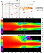
I spruced up my H-array simulation to use as a reference for comparison.
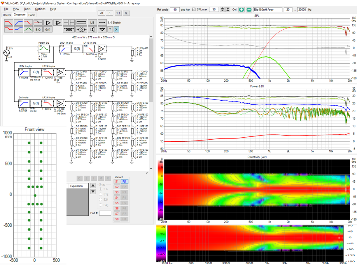
Its a lot of drivers (20x5FE120) so its understandable why I would want something simpler but power response and DI are good and the vertical pattern control is almost line array like. At center height, the peaks and valleys due to floor and ceiling are less than +/- 2db below 1 khz. The overlay traces in the center graph are for +/- 200mm vertical offset from center and are impressively close together below 600 Hz and +/-3db near 1 khz.
This sim was based on a 482 x 272 elliptical waveguide I did early in April as I was learning ATH and ABEC. I see this waveguide has less of a hump in its DI, which might allow it to integrate better in the simpler system configurations I've been looking at recently.
Attachments
I mean this, it looks to me like the black area comes from the rim array side of the crossover which I took to be the narrowing of directivity from cancellations of the arrayed drivers at that frequency.Main null? Not sure what null you are talking about. Due to arraying? I doubt due to CTC between array elements. I tried twice as many drivers at half the spacing and saw no change other than SPL.
This should help that problem 🙂The Aries M is/was an impressive effort for DIY. I would get more out of the article if I read German but I can read the graphs and a few key words here and there.
Aries M Dokumentation - PDF Free Download
Nothing I said should be taken as suggesting those efforts are misplaced. For me I am not clear on which of the problems we cannot avoid or are more detrimental overall to the sound from the speakers and room combined. Two things I have tried highlight this to me. I don't like much lateral reflection, it can have a pleasing effect on some tracks and I can see why people like it, but for me overall it is more distracting. Some early reflections help with the cross talk issue which I do find to be a problem with the array and room treatment combined. The right combination of reflections still isn't clear to me.As to the room predictions, I've read research that says reflections, especially lateral reflections, are helpful as well research that finds that the first order floor and ceiling reflections do affect timbre and localization. That indicates that my efforts to control the vertical aren't entirely misplaced.
The second is the dreaded comb filter from the arrays. It is a problem for the eyes much more so than for the ears. I have no doubt that the shading will make some improvements even if it just helps the eyes 😉 When the weather in the Netherlands improves some listening reports will be welcome.
Attachments

I used "misguided" ironically; not due to anything in particular you've said but in consideration of everything I've heard and read. I think, though, that Kimmosto would characterize it that way not that he would actually say so. He apparently would prefer to treat the room. Regardless, its been educational.
Array combing is indeed more for the eyes than for the ears and indeed more in simulation than in measurement. And if that is true for array combing, should it not also be true for combing with boundary reflections? But perhaps so only if we allow sufficient reflections/reverberant sound field to mask them (or replace/augment reflections with ambient drivers).
Certainly deep nulls in the bass and low mid bass are best avoided but how far is it necessary to go to eliminate them and what if we stop short of that level? That is what we are exploring. Let's keep doing that now with appropriate attention to the power response as well as the axial and predicted in-room, ignoring known pessimistic predictions, certainly those above 2 khz.
Re' the weather in Netherlands - we are also looking forward to listening reports on a waveguide two way that will help answer the question of how far to go.
I've fired up the heater to paint today 🙂.
For me there is a big difference (in what I want) for the early wave front and the later reflections. My original goal (which I pretty much achieved) was to get as clear a shot of that early wave front. But to achieve it in a sparsely treated room meant to have speakers that could work with the room. Nothing new here.
Before I actually got what I wanted, I never stopped to think what it would mean for perception. There should be a difference between combing from reflections and combing inherent in the design. That's the reason to try the shaded approach. It will move combing further up the frequency chain, not stop it completely but close.
The later reaction with reflections in a room will also cause combing, but it mostly arrives late enough to keep the average balanced.
Not true for bass notes, as they haven't fully developed when the reflections start messing with it. In other words, with a floor (or ceiling) bounce you did not get to hear that first wave front undamaged, before the rest hits you. We will be pretty used to that kind of thing though, as an instrument or voice in the room itself would have similar properties (have it's own floor bounce). My theory was that if I remove that bounce, it would get me closer to hear the bounce (if there is one) in the recording, hence making it a "you are there" kind of experience.
I can say that part works. But having some level of reflections probably isn't a bad thing around the cross talk frequencies. Unless you listen up close, real near field.
I like (actually love) the "you are there" kind of experience. It's very persuasive and sucks you into the recording. At least, that's what it does for me. Which means I'll be looking to improve upon that, maximize enjoyment of that specific feature. Which means accepting there's work to be done to hide cross talk effects. Mid-side EQ combined with ambience goes a long way, I could live with that, accept it as the end station. However I am curious if more is to be had, so expect many more experiments to enhance the "you are there" type of presentation from me.
That's why the only other route I'd ever investigate would be a Synergy that plays low enough (it will have a higher reflection level to floor ceiling (*), but never distracting as you still get a clear shot at the original wave front plus reduced levels of reflection compared to direct radiators. (actually it will help hiding cross talk) For lower notes it would be coupled with multiple drivers to be able to avoid the floor/ceiling bounce. Multiple ways to do that, never really easy though. One woofer does not stand a chance, multiple (smaller?) woofers do. Just like mic averaging, you get different bounce frequencies that level each other making it act like it's not there.
(*)= floor to ceiling array does not have less reflections, but it does act differently.
Anyway, time to go into the garage...
Anyway, for me it beats the "what woofer for this 2 way" kind of worries. I don't expect the answer to be in that kind of thing.
Last edited:
well i'll wait till you get a chance to play OU812 and can describe how it makes you feel....
if all the fretting over the technical's doesn't elicit a subjective response what was the point of the exercise??
if all the fretting over the technical's doesn't elicit a subjective response what was the point of the exercise??
It's all about the subjective experience in the end. At least for me. Emotion is what music is to me. But it starts with a technical journey to get close to the essence. The magic is in the music, not in it's reproduction. Reproducing it is a technical matter. But not that easy and with lots of little nuances...
Last edited:

Is it a bingo? 😀
Much better than the single woofer, I'd say. The one thing I'd research would be if the direct wave front looks as promising (removing the reflections).
Much better than the single woofer, I'd say. The one thing I'd research would be if the direct wave front looks as promising (removing the reflections).
Me too, recent renovations on my house took a time consuming turn due to old termite damage so a week of leave I had set aside for playtime vanished.we are also looking forward to listening reports on a waveguide two way that will help answer the question of how far to go.
When I built the CNC mechanically I wasn't happy with the v wheel setup. I could see that was going to be a source of inaccuracy and annoy me over time so in the spirit of doing it properly once I have ordered the upgrade kit for linear bearings, thicker, taller plates and a better leadscrew tension system. I've also got a lot of aluminium extrusion and some birch ply to make a proper table top and enclosure.
One idea I have had recently is to make something a little like the Genelec W371 in layout, somewhat inspired by the GGNTKT cardioid response and also kimmo's suggestion that cardioid all the way down is a good solution.
I've got the Dayton 15" RS sub drivers which I could put on the back at the bottom of a cabinet with the Faital 15 on the front up high to meet the horn at the correct height. The Faital will go down nicely to 60 Hz or so in a small sealed box and the rest could be for the sub. Some force cancellation and the possibility of making an active cardioid response over a reasonable range as the RS can play quite high.
If I weren't planning corner location, I would likely choose cardioid. Some time ago, Kimmosto showed me how to model it in Vituix:
https://www.diyaudio.com/forums/software-tools/307910-vituixcad-224.html#post6279895 post 2236
The Genelec woofer is interesting. I don't see how it can do all that is claimed adding just a rear firing vented woofer to a waveguide 2-way.
I imagine your CNC will be an endless source of both kinds of fun. I was blessed with friend with a CNC but he retired and sold the machine a couple of years ago. After you get the table done, you'll want to add vacuum hold down to it and then there is the dust collection system to optimize and figuring out toolpaths. The one thing I didn't get into was 3D milling for waveguides but that is where I would want to go if the machine were still available to me.
Interesting that a pretty good low end cardioid response was achieved with just an LR2 lowpass.
What claims have you seen for the Genelec Woofer box? It's designed to go with "The Ones" which are a three way themselves so the woofer box would make it a 5 way. Genelec have a pretty comprehensive room and speaker EQ management system built in.
In the video I saw them talk of it having two modes a complimentary one where the two woofers act independently based on measurements taken in room, or a directivity mode where the directivity of the One speaker is extended lower down. The directivity mode sounds more interesting.
I doubt there will be a vacuum holding system for my CNC but I am building an enclosure and a dust shoe. The enclosure is needed both ways, to protect me from the dust and the CNC from everything else that lives in my workshop and comes out when I'm not there 🙂
I would love to see what it does (both cases) in a simulation. Especially the part where the room is involved. As seen by Jack's latest sims, two woofers do better than one as far as mitigating floor bounce. Likely, the Genelec double woofer can have the same (or similar) effect, but can also act as a cardioid extension.
I'll admit being a little surprised by the latest sim from Jack, as I was kind of expecting the woofer center to center spacing being too large to have a proper effect. However at a distance, that difference (from each woofer) to the listening position diminishes and it can still work. The bottom Genelec woofer will be even further away, so I do wonder what's up with that. A little manipulation would go a long way, but in a Genelec system I don't expect to see (the allowance for) much latency. So there will be a limit what can be done.
Edit: the inverted woofer on the back might explain good results even with the difference in distance. Still wonder about the floor and ceiling effects, in the case of the Genelec.
And for placement: how far from a back wall would be enough to get the proper effect. If it does act like the VituixCAD prediction it would work quite well with a horn reaching low enough. (be it a horn with rim drivers or Synergy or just a big (two way?) compression driver)
Last edited:
what claims? "steerable acoustic directivity" seems exaggerated
How else are you going to sell them. At least this isn't completely inaccurate, it is a form of acoustic beam steering if it is a cardioid pattern. And if it has two modes it is adjustable. 🙂
It struck me that the waveguide I've designed is about the same shape as those SEOS18s I have in storage next to my TD12Xs. It was an easy manner to spin a version of the RimSlot 3-way to use the 465mm x 213mm SEOS18 instead of the 400mm x225mm ATH waveguide. The results were surprising because per its spec, the SEOS18 starts losing V control near 2 khz.
Axial, power response and DI after optimization are very similar to the ATH WG. The SEOS18 system has the same belly in the power response around 1 khz as the other. Optimizing it made clear that it was due to H directivity mismatch in this region. It was reduced first by reducing XO as low as I dared, next by making the XO asymmetrical and finally by a couple of PEQs. I ended up with CD high pass 862 Hz LR48 and RimSlot low pass 1000 Hz LR24.
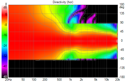
Comparing vertical directivities:
SEOS18 system
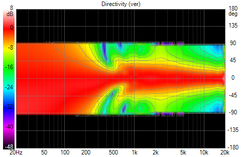
Rect400_140 system
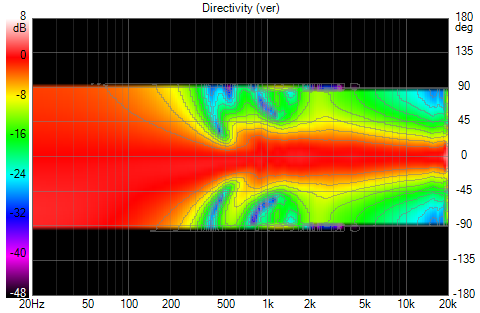
Axial, power response and DI after optimization are very similar to the ATH WG. The SEOS18 system has the same belly in the power response around 1 khz as the other. Optimizing it made clear that it was due to H directivity mismatch in this region. It was reduced first by reducing XO as low as I dared, next by making the XO asymmetrical and finally by a couple of PEQs. I ended up with CD high pass 862 Hz LR48 and RimSlot low pass 1000 Hz LR24.
Comparing vertical directivities:
SEOS18 system
Rect400_140 system
Attachments


Going back to Genelec for a moment - the first thing I did after reading the manual was to try an independent filter/amplifier channel for each woofer. I was not impressed with the results. I got better results with the woofers in parallel. Perhaps independent channels would help with a wall null that necessitated a compromise. My hat is off to Genelec if their integrated speaker management software does this correctly automatically.
Regardless, I will use a 4-pole Speakon for the woofers to preserve the option. I actually need separate amp channels for these woofers as my fanless amps have the same maximum power output with 4 and 8 ohm loads.
Regardless, I will use a 4-pole Speakon for the woofers to preserve the option. I actually need separate amp channels for these woofers as my fanless amps have the same maximum power output with 4 and 8 ohm loads.
If you've ever owned an amp with a noisy fan, you know they can be. I don't want any fan noise adding to the background.
Now I have a more compelling justification for that additional amp channel. By extending the cutoff of the upper woofer to 1 khz and using a low slope filter, I got improved vertical response above 1 khz, due to the woofer overlapping the DMA45s above 600 Hz.
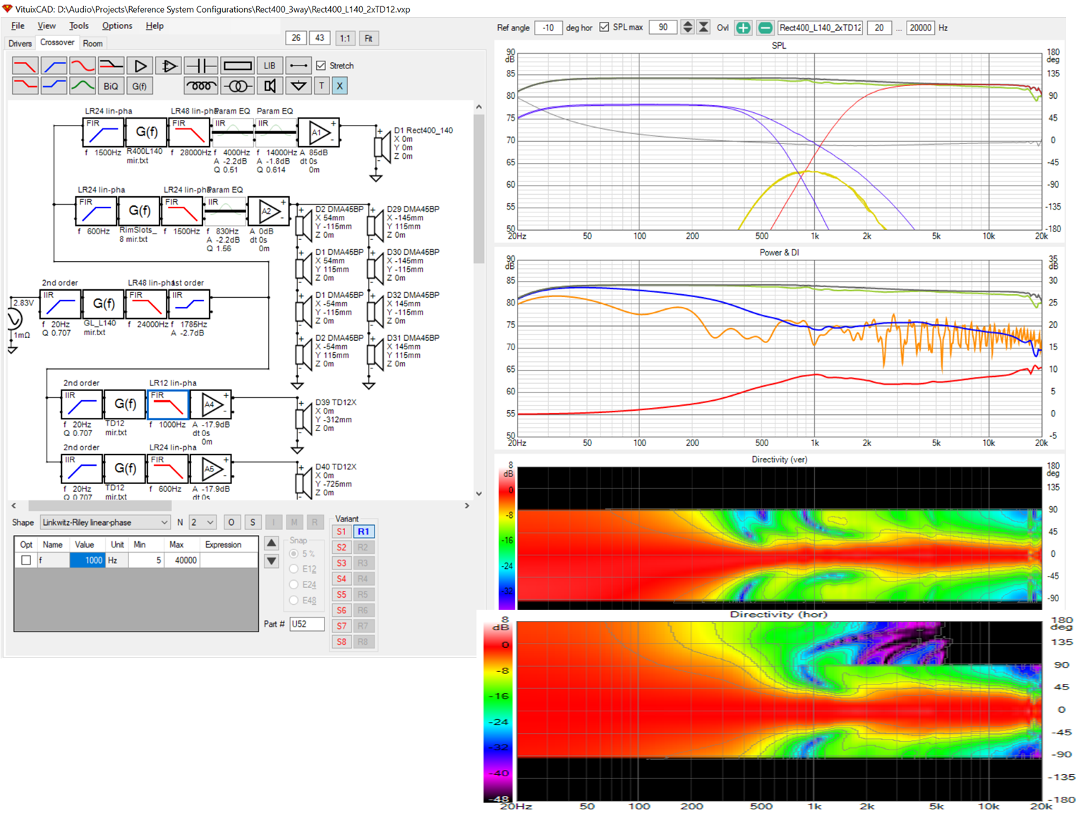
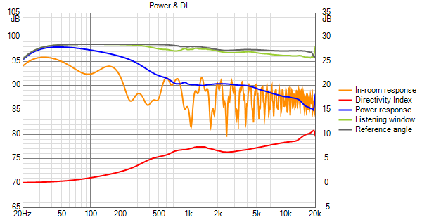
The power response has a small rise in the 2-5 khz region that has been mitigated by tiling the axial response down. The predicted in room response is flat though so perhaps that axial tilt is a good thing. Ultimately it will be tilted to taste.
This hump in the power response has plagued me through multiple waveguide variations and innumerable equalization iterations. I believe its due to the waveguide vertical response widening. That widening is counteracted by overlap from the DMA45 array, low passed at 1500Hz, and upper woofer on the slopes of their low pass filters. If I got the slope of that decreasing overlap exactly right, the power response might flatten out completely.
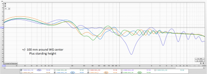
The response variation with vertical offset is impressively low:
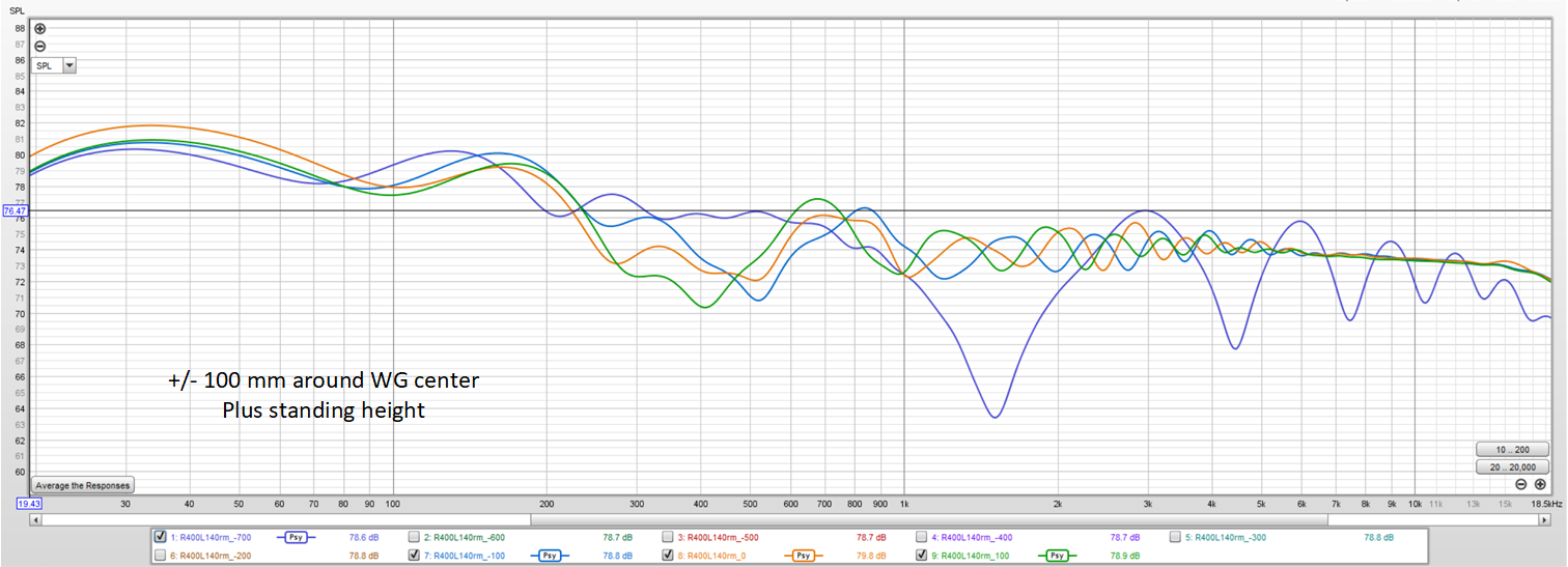
(that is 2 db per major division in the REW screenshot)
The variation maximum at just under +/-2 db around 300 Hz and better that +/-1.5 db elsewhere for waveguide center at 900 mm +/-100mm. The standing response looks good if the large flooe combing nulls above 1khz are ignored.
The power response has a small rise in the 2-5 khz region that has been mitigated by tiling the axial response down. The predicted in room response is flat though so perhaps that axial tilt is a good thing. Ultimately it will be tilted to taste.
This hump in the power response has plagued me through multiple waveguide variations and innumerable equalization iterations. I believe its due to the waveguide vertical response widening. That widening is counteracted by overlap from the DMA45 array, low passed at 1500Hz, and upper woofer on the slopes of their low pass filters. If I got the slope of that decreasing overlap exactly right, the power response might flatten out completely.
The response variation with vertical offset is impressively low:
(that is 2 db per major division in the REW screenshot)
The variation maximum at just under +/-2 db around 300 Hz and better that +/-1.5 db elsewhere for waveguide center at 900 mm +/-100mm. The standing response looks good if the large flooe combing nulls above 1khz are ignored.
Attachments
- Home
- Loudspeakers
- Full Range
- Full range line array for wall or corner placement