For the ground lift you have a choice:
1. Diodes/ bridge + 10R resistor + cap or
2. CL60 (or equivalent) + cap.
I have used both methods on different amps.
Rod Elliot's site is a must site to visit when building amps.
There is a thread with quasimoto values for various transformers, if that helps. Cannot find the link as I'm using my phone.
I would use 63volt caps. They will handle ripple and voltage fluctuations much better than 50V caps.
Hope that helps.
PS later you will need to look at a soft start and speaker protection😀
Many thanks Harry3
Yep, know Rod's website, and most comes indeed from there, while some points are not necessarly up to date though IMHO.
Hence me appreciating your advice: so CL60 + cap works as well as the recommended bridge?
If so, no brainer, CL60 it is! Well noted with cap...
Main caps, voltage... will dig again into it...
Quasimodo, yep know that separate thread but the trannys I have in mind aren't sadly there in the same VA and voltage spec. I was thinking Toroidy... just following others, never tried these so far. Wonder if the Quasimodo is really something people do: did you in your USSA?
And yes, soft start and LS protection... as things are I already purchased these! As the boards and the transistors and other bits that... was just hoping to follow one in the build before dimensioning everything else, just having to fine tune... lazy me 🙂
Many thanks again for your help!
Claude
Hi Claude
These are 63VDC 35mm diameter caps that I have used before:
https://www.digikey.ca/product-detail/fr/EKMH630VSN153MA63T/565-4208-ND/4000661
https://www.digikey.ca/product-detail/fr/ESMH630VSN223MA80T/565-4899-ND/4002921
They’re are other ones with screws but I believe you have not specified yet if you will use a PSU pcb or not.
Fab
Hi Fab,
Thank you so much for your kind post and help!
Indeed these are both very good caps!
I won't use screws but will have to be inventive re board (just as base / support) to hold the caps firmly in place while using wires I will solder to connect all properly directly.
As ever, your advice to go for 63V caps for this amp is spot on. I will detail why in a coming post so everyone can benefit from it in the future. I am learning...
I have 1 question though regarding the caps you recommended, more for my understanding. Ripple value, their rating... this gave me quite a headache. Read so many things, did calculation and then people tell you to take x2 or x3 DC need. I don't know what to believe, I went for say 200W@3R splitted in 2 rails, and ended up with some factors with 12A ripple needed for the cap (bank) before the R of the CRC. On the other side there is for sure a surge at start up, but then the caps are probably OK for some one offs. nd the R is low so perhaps ripple value can be splitted... argh!
I can see the caps you recommended are rated for 4,88A, resp. 8,94A. I can also read there is a factor to apply that "helps" this rating for lower temps. I have no clue what temps the caps will see, but of course less than 55° per definition as that's the hot spot of the amp.
Fab, are either of these caps OK regarding ripple dimensionning for 150W@4R, even in the worst case of 15000- R- 15000? If it is not too long or too much asking, just for my understanding, what ripple value are we deeming safe re caps spec in my case?
Given their price, longevity (especialy given their high temp rating that makes it look even better), I even could be tempted by 6x 15000uF per channel.
Many many thanks again Fab, really appreciated, this project is also for me to learn on super amps...
Claude
Last edited:
At that stage no one should be stupid enough to listen to me instead to Fab, LOL, but just in case someone wonders why it doesn’t indeed make a lot of sense to go for 50V caps for this build, unless really needing a high DF. Indeed, given the resulting power enveloppe, and noting the difference doesn’t translate in a lot more soundpressure, one would run very close to USSA territory. Let’s see why…
Let’s say you want caps rated for 50V. On a constant basis you want some safety margin, say not running higher than 45V « whatever the case ».
Lessons learned, mains fluctuates by 10% and I found out that the regulation of toroïd transformers could be anything from 4% to 20%. Despite mine being probably Audio grade by Toroidy or similar, an apparently reputated company for these devices, they give no figures. Let’s assume 15%, regulation, which is not VG but we need some safety in our guesswork. And if it turns out to be worst, then we have 5V margin, remember. One can’t just take all the worst cases and add on top a lot of margin everywhere, would end up being silly.
230V that can become 253V, 45V max at the rails, that means max 46.2V before std bridge, means 32VAC tranny as next value. But 15% regulation means less than 28VAC max, so say 27VAC tranny to go really safe.
Aouch. 27VAC tranny translates in nominal conditions to +-36.7V at the rails… best cases. Make that a bit less due to the CRC and other bits not being perfect.
Only Fab can say how 36V at the rails translates into power, but my understanding is it is likely to be somewhere around meager 96W into 4R. And now if the mains fluctuates down, that is we get say 215V, then you probably get less than 85W into 4R.
OK, perhaps I was a bit quick with my kitchen table reasoning but you get the idea and you could still run exact calculations.
Bottom line: buy yourself some headroom and go for 63V caps… or if you don’t need much power into low impedances and a high DF why not looking at the USSA range ?
Amending the schematic to 63V caps and also cleaning other bits while at it…
Claude
Last edited:
Latest version... some cleaning around the plug / entry, probabaly will refine some values re bleeders but I guess we are getting close.
Need to think re quasimodo and small bypass caps... need to find a tranny, might go 400VA
Hope it is useful to others with the same existential questions re how to get started
Claude
Need to think re quasimodo and small bypass caps... need to find a tranny, might go 400VA
Hope it is useful to others with the same existential questions re how to get started
Claude
Attachments
Last edited:
Hi Claude
There are 3 caps in a CRCC arrangement, thus 3 times the ripple current capability of one cap. 12A ripple current per cap seems a lot. 200Wrms /3 ohms is surely very rarely to occur since it is probably where the amp would start to clip and you do not want to listen to that for an extended time ....otherwise you can go nuts 😱
For transformer regulation, a 300-400VA will normally give a much better regulation than 10%. See below an extract of Antek 300VA 32VAC transformer:
Load Test (operation test):
TEST CONDITION: Input 120VAC 60Hz to the primary coils (in parallel), Output 1 and Output 2 in parallel to load, and measure voltage and current at different load levels.
Voltage output Current output
32.6V - 0.0A
32.0V - 4.1A
30.9V - 9.3A
As for main line voltage you should assume your required power based on the average target voltage value from your electricity provider. The maximum voltage should be used for the safe margin of your components (and heatsink temperature). For the minimum line voltage you would get a little smaller power amplifier value but so what.? 🙄
have in mind that you need 4 times the power to get twice the sound pressure level...
Fab
Last edited:
Ah, that's all interesting... and possibly where the diference comes from regarding ripple!
What I did... I thought 150W into 4R as whatever comes on top is more short term reserve from caps on bursts into low impedance and then the transistors have a limit anyway. Say a tad over 6A needed, 2 rails to provide current, makes a tad more than 3A per rail. Not having any clue on audio I would have thought"take whatever value from 4A re ripple and you are done".
But then I thought the R from CRC was slowing the current for the next caps, so that the first C would suffer the most from ripple. OK, make that 4A for that one. And then I read that one should take 3 times that value to be safe! OK, understood that these rules where perhaps rather applying to Class A amps driving all the current all the time, but then nothing re Class AB being different was specified. Hence 12A and me very :-(
Now I understand reading you that even if the 12A ripple should be considered (?), the 0.1R of the CRC is probably still negligeable despite being 10 times more than ESR (but probably 10 times less than the cables to it), so that the 12A can be splitted between ALL the caps. I was considering 2 caps for the first C just because of that ripple, whereas as low pass I would rather like to see them after R should I fit them. All gone now, it is either 15000- 0.1R - 15000 or possibly 15000-0.1R-30000.
Last but not least, great values from Antek: that's less than 6% regulation. Have to see what tranny to use... Toroidy came as recommanded, but no specs, need to dig into that next. And 400VA tranny is not a lot more than a 300VA one.
Indeed, mains fluctuation and max power, as said I don't care if I have 150 or 130W as negligeable in terms of sound pressure. All I need (not even sure I need it really LOL) are probably 70W with the ability to drive very quickly low impedances effortlessly.
This, and the fact I want a Class A bias as high as possible while remaining safe re temp and longevity, means that I will stick to the 42V DC rails although 63V caps could allow more. In fact, the other bits to sort now are heatsinks and chassis (and possibly tranny while at it as big parts). That dimensionning will dictate how much bias I can take and what casing parts to use.
Next one the list... whenever time permits it
Many many thanks, I feel I have progressed a lot in defining the right values for the PS
Claude
no need c6 to c8 since u have snubber.Latest version... some cleaning around the plug / entry, probabaly will refine some values re bleeders but I guess we are getting close.
Need to think re quasimodo and small bypass caps... need to find a tranny, might go 400VA
Hope it is useful to others with the same existential questions re how to get started
Claude
There is a list of quasimodo transformer test... just look for the models and use it
Hi Anthony,
Thanks for your kind mail.
You are correct, that's one point where I need to make a decision. In fact, if having the real quasimodo snubber, I possibly don't need (let's take one rail as you did) C5 to C8. In fact, I would not use C9 and C10 either. I would though have other caps instead of these to get the 3 components required by the proper process by Mark.
One might even wonder in that perfect case if C15 is really needed... any POV on this BTW?
NOW to the big issue I have: this would all be valid IF I had a quasimodo jig (cheapmodo easy to do, I could do that indeed)... AND a scope that goes into the 10MHz range. Unfortunatly my scope doesn't cope with that, it is say limited to 150kHz-200kHz. I am not sure I can find another to borrow, that's the BIG issue here. And yes, I did already looked into the thread and none of the transformers I am considering has been sadly tested, bad luck.
I found a post where someone used a "2 component only" overdamping snubber that suits it all, which I used for a small project. But I am not convinced this is the way forward for big VAs. Everyone would just go for these std values otherwise I guess? So I presule one needs really to measure properly to find out what Rs to go for and use the 3 component snubber Mark suggested. Right?
BUT IS ALL this worth the effort? Can one hear it... vs say no measurement/no quasimodo snubber and just the traditional "easy fix" bypass diodes as on the schematic?
Fab, Anthony: do you went quasimodo in your amps? Or just diode bypass caps? or whatever? What have you used as bypass in real life from C5 to C15?
That's where I need your practical experience. I am progressing slowly on this project (very busy with work and family, I had hoped to be a follower) and if I start smaller projects such as quasimodo I might never see the end of the initial target project. Having said that, if quasimodo is best pratice today and part of the learning process, I will just include it as small project and spend time on it, looking for a better oscilloscope... just don't want to do it for the sake of it.
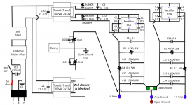
While I don't have the answer to snubber OR traditional bypass caps, I have this provisory schematic "that includes it all", well noting that it will be either snubber OR bypasses. Was in colour as options in the first schematic I did, kept just admittely "snubber" in the last one, as reminder 'not done on that'...
Advices are welcome!
Thanks again
Claude
Thanks for your kind mail.
You are correct, that's one point where I need to make a decision. In fact, if having the real quasimodo snubber, I possibly don't need (let's take one rail as you did) C5 to C8. In fact, I would not use C9 and C10 either. I would though have other caps instead of these to get the 3 components required by the proper process by Mark.
One might even wonder in that perfect case if C15 is really needed... any POV on this BTW?
NOW to the big issue I have: this would all be valid IF I had a quasimodo jig (cheapmodo easy to do, I could do that indeed)... AND a scope that goes into the 10MHz range. Unfortunatly my scope doesn't cope with that, it is say limited to 150kHz-200kHz. I am not sure I can find another to borrow, that's the BIG issue here. And yes, I did already looked into the thread and none of the transformers I am considering has been sadly tested, bad luck.
I found a post where someone used a "2 component only" overdamping snubber that suits it all, which I used for a small project. But I am not convinced this is the way forward for big VAs. Everyone would just go for these std values otherwise I guess? So I presule one needs really to measure properly to find out what Rs to go for and use the 3 component snubber Mark suggested. Right?
BUT IS ALL this worth the effort? Can one hear it... vs say no measurement/no quasimodo snubber and just the traditional "easy fix" bypass diodes as on the schematic?
Fab, Anthony: do you went quasimodo in your amps? Or just diode bypass caps? or whatever? What have you used as bypass in real life from C5 to C15?
That's where I need your practical experience. I am progressing slowly on this project (very busy with work and family, I had hoped to be a follower) and if I start smaller projects such as quasimodo I might never see the end of the initial target project. Having said that, if quasimodo is best pratice today and part of the learning process, I will just include it as small project and spend time on it, looking for a better oscilloscope... just don't want to do it for the sake of it.
While I don't have the answer to snubber OR traditional bypass caps, I have this provisory schematic "that includes it all", well noting that it will be either snubber OR bypasses. Was in colour as options in the first schematic I did, kept just admittely "snubber" in the last one, as reminder 'not done on that'...
Advices are welcome!
Thanks again
Claude
Last edited:
It appears I may answer my own questions LOL - of course I would still welcome any comment though!
The following is open to discussion, but after having spent a hell lot of a time on audio forums, technical forums, Neurochrome's website, Rod Elliot's website and done many many calculation to feel more confident rather then just relying on posters (as I couldn't really test in vivo), I am now thinking:
- Snubbers are not needed, they won't improve the sound, more EMI affair
- Given "reflexions on both sides of a tranny", I am pondering if it is not C20 "OR" C9+C10, instead of "AND"...
- Pretty academic, as I start to suspect that these caps will have 0 impact on sound and are just there for EMI... of so they might GO, same as the snubbers, and only be considered again IF there is a problem
- Wondering if the bypass caps around the diodes of the rectifier have an effect and if positive (taming and getting garbage down from few MHz to 10KHz might be great fro EMI but otherwise???)
With all this I might end up with the same PS... as the one I built 3 decades ago for my amp and nothing has really moved on!
OK, I learned a lot of things in the process, that might be useful one day, and there are in fact a couple of changes in 30y:
1- The use of 2 bridges/rectifiers instead of 1 with a much better grounding scheme understanding (at least public and for audio), and that CAN matter quite a lot in my experience... so I will go for 2 bridges unless adviced against
2- The fact electrolytic cap's specs have improved massively (but on longevity, that's a manufacturing process issue), meaning that (for THIS poweramp, not mentioning HF DACs etc.) intermediate bypass caps to the big cans might not be needed or even be detrimental. That's new and against my experience, admittely not with the latest high quality big caps. I can postpone that matter anyway as A) the real bypasses and possible impact will be on Fab's board at the end of the line (well downstream the CRC board) and the question will be wether adding an intermediate bypass or not between 2200uF (or so) and 0.1uF, B) I can still make a provision for potential additional bypasses on the CRC board under the caps - should I really fancy trying that aswell one day
3- Given the progress made in 30y with caps, I shall dig into the rectifier's specsheet to see if the small diode bypasses still make sense today. I don't want for a power amp individual diodes, I want a bridge, so that rules out the soft recovery options (sadly, I use them since 20y in all my small power audio projects) => ADVICE WELCOME
On it... hopefully a lot of the overengineering will be gone, not mentioning that today there are even female mains plugs that include a holder for the fuse and a line filter (wonder if any good and working both ways without penalty to the sound though, advice?)
Claude
Hi Fab,
I did a lot of cleaning work on my schematics, getting rid of almost all bypass caps and snubbers, as these are either complicated for little or just EMI. Changed orders of a few things and dimensionning... learned a lot.
The last bit I haven't decided yet is around the bridge. I can't find my answers in the spec sheet. I read that using 0.1uF bypass arount each diode was a good practice... but then I looked very hard at most pix posted on this forum, at tens of builds... and I can't really see anyone using these!
Question: do you use bypass caps for each diodes of the bridge in your builds... or not?
Fab, just looking for your best practice: I won't bother your with justification or debate, simple yes / no would be fine. This is the last PS question I can't resolve: you are the designers, you build amps and you know bridges... I will simply comply!
Many many thanks
Claude
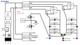
OK, that's what I come up with... lots of cleaning work.
No more bypasses around bridges etc., as that seems to be the practice nowadays, no more snubbers etc.
I have seen some fitting a 0.01uF cap in front of the primary of the transformer (or is it at mains between L & N for both transformers?): I wonder if you go for it... or not. Please let me know.
That's probably my last point re PS, so if you spot anything please shout, any help is greatly appreciated!
Many thanks
Claude
Attachments

Many thanks 🙂
Yep, at the end it is exactly what I would have done 30y ago, apart form the "double bridge" and the "Earth".
So much for progress LOL!
Still pondering if an X2 0.01uF cap is suitable at the primary (ies?), as that is also new... EMI stuff & Co...
If that is fine then I need to look into real life parts and connectors / wires (what dimensions???) for the BOM and depending on that also heatsink requirement... another black hole.
That will have to wait though, busy at the moment, but I already secured ALL parts (all transistors, accessories such as soft start / DC protection, small heatsinks) except those that can be purchased at Mouser's and the entire casing with heatsinks. OK, and the copper wire for the output coils and various connectors and cables.
It is really very time consuming to plan for all the bits that come on top of the amp boards (which in itself is a well documented part, but not the rest)... Is that the reason no one got really started after the GB?
Kind of "you have a top engine, but it is up to you to get it running and to install it in a proper chassis... to get a car"?
Anyway, on it... and will report so that some may benefit from all this, it is just I had hoped not to be the first in the GB to gest started / report...
Enjoy music and life
Claude
Last edited:
My $0.02.
Leave room so you can add the Quasimoto components near the transformer later.
Also later if you are inclined, you can get rid of the diode bridges and use LT4320 based rectifiers - expensive.
Only you can judge if these mods are improvements to your system.
Good luck and don't over think this project.
Many thanks for your kind reply Harry3, always appreciated 🙂
As this is DIY there should be enough provision for some extras afterwards, should I need them.
Having said that, I was keen on quasimodo as this appealed to my engineering side and I liked at the results I saw. Then I looked into the frequency range and wondered if all that would have any audible effects at all! Then looked into Rod's site, and other posts... and I have yet to find someone reporting some audible benefits. Do you have perhaps a link or a post that illustrates some real life audible plus?
LT4320 based rectifiers... I must confess, I don't see the point. I get the tech allright, I see the benefits on the paper, but at these (still moderate Class AB) power levels the complexity vs something bulletproof that does the job more than well enough at these low frequencies... I don't know, another engineer's game? Having said that, IF someone can report a real audible gain (my sole interest) in a PROPER oversized PS, then more than willing to jump ship.
You see, at the end, I am not over thinking this project at all anymore, on the contrary: clear real life gains vs hassle approach LOL.
I really have to follow your and Fab's advice not to over engineer things as I have to plan all from scratch for the first time in such depth... as otherwise nothing would progress. Having said that, there are for more complex things in life 🙂
Thanks again for all your help
Claude
...It is really very time consuming to plan for all the bits that come on top of the amp boards ...
Is that the reason no one got really started after the GB? ...
Claude
Time consuming indeed...😀
I started a while ago this promising amp, but way too many projects at the same time: Loudspeakers (3 pairs)+ amps (Class D+ FSSA)+ preamp (B.Putzey's)+ headphone amp (The Crocodile)+RPI /Moode player+house arrangements+outdoors+...work(!) All at a time keep me progressing at "snail" pace on each of them.

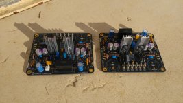
Here's where I am at it (no progress during last 2 months I confess)
Attachments
Hi Claude
I put 100nf across each AC connections of both diode bridges.
For the “Quasimodo” circuit, I had installed it in my FSSA1 but could not notice differences with or without it....however I must confess that I have only installed the typical default parts value and not the optimized ones -I have not mounted the test circuit.
Nice start Kalamin
I also use a better sounding input cap nowadays: Nichicon 2.2uF QAP2E225KRP or 1uF is ok too. They are also the perfect size for this pcb.
Do not forget to follow the manual and test in sequence : input stage, driver stage and then output stage. This is the way to have it working without issue once fully assembled.
Fab
Last edited:
- Home
- Amplifiers
- Solid State
- FSSA amplifier build thread with review