Hi AnthonyA
I specify the real measurement with my own PSU used in the amplifier, I am not in the marketing area😉
Fab
I specify the real measurement with my own PSU used in the amplifier, I am not in the marketing area😉
Fab
Whaou, many thanks for this very clear and detailled reply Fab!
You are the one, pleasure to learn from you!
Back to my drawing board
Claude
You are the one, pleasure to learn from you!
Back to my drawing board
Claude
Ok, so here is a draft of the PS schematic to feed Fab’s boards. I did it best I could : this is my first try at it and I hope it is understandable. I tried to gather tons of material I read here and in books.
There are quite a few points to be discussed… at that stage all can be modified, so thanks for your help !
1- None of my low power devices have an Earth connection, they are just 2 wires to the mains. None of my current power amps have an Earth connection, they are all of the 90s and run fine (same power levels as here). I used to have power amps with Earth connection when in Germany but there they have Schukos / plugs that enable you to plug one way or the other (switching L and N), whatever sounds best (lowest leaking voltage). The country I live in now doesn’t enable that : the plugs are just to be plugged one way. For that reason, plus the hassle of Grounding issues, plus the complication to go into something I never experienced, I stuck to 2 wires (L and N) plug. NOW FIRST QUESTION : is that OK ? I am willing to do whatever the designer recommends re PS, so Fab & Co just let me know… you will anyway get some questions re wires
2- I though left a provision for Earth (that doesn’t exist at this stage) as I copied something I found re casing connection. I left it there until point 1 is solved. We shall see if or how to correct this section if no Earth.
3- Rs and Cs is a snubber at the outputs of the transformer. Well, I fitted some on my low power RIAA amp’s PS. Can’t say if it does make a difference, assume it could perhaps with big toroids ? Anyway, I don’t want to go the hassle of measuring the perfect snubber so I just went for std values that are supposed to be « fit it all » as in the snubber thread. POV ? Do you use some ?
4- C3 & C4… are these really needed ? Found them in the litterature, I assume they can’t harm, but well. Should they still be fitted? Even if we keep the snubber ?
5- Diode bridge. Nightmare. I have found people advocating 1 bridge, as I did here, but others advocating 2 bridges. I must be a very tired and not clever engineer as I can’t really see why this should make ANY difference at all in terms of rectification provided of course 1 bridge can cope with the full load. I could perhaps see a difference with the tranny shield and grounding, kind of floating thing I had once… but I have no clue if that affects the sound. What are you guys going for ? I will just follow your advice! Tell me if I need to change that, I don’t mind an extra bridge as long as it is better…
6- C9 & C10… are these needed ? Don’t care bout the price, just the sonic…
7- Bleeders, R1& R2… I went for 4.7kR and 2W. Is that OK ?
8- I don’t know if I should go for a CRC or CLC filter. On the paper CLC with 2mH vs CRC with say 0.2R (found in the litterature, but way higher than what Fab recommends), wins clearly to filter the mains. On the other hand, I also read some negative oscillation comments with CLC, complications and mitigated results. At the end, to quote Papa (was for 100W amps and my guess would be more for Class A with permanent loads), CLC or CRC doesn’t matter as long as you have at least 25000uF as last C, as that determines the sound. Whats your POV ? I can see that Fab recommends both… Fab, did you notice any sound difference for this Class AB amp? CRC seems easier to build and affordable, but then what value to chose between 0.1 and 0.22R and what are the trade offs apart from losses and possible fluctuation with I ? No clue on CLC but willing to learn if required. If so, what part to go for? I found only that 2mH one https://www.mouser.fr/ProductDetail/Schurter/DENO-23-0001/?qs=A5k8bsa1loCgxv5nVtXMcg%3D%3D
9- Main caps. To make things easier I draw here as a starter « 15000uF – R or L – 2x 15000uF ». Low ESR high ripple caps. I might go for much more than that, thinking 2x15000 – R or L – 2or3x 15000, the former to cope with high ripple, but let’s see the principle first. That is already quite a lot in terms of caps as there are 4 modules like this in the entire power amp, the slow start will have work. Comments ? Does it make sense to add more caps than on the drawing ?
10-R5 & C18, and R6 & C19 are again snubbers I found in the TI spec sheet with these values. Wonder if really needed, never went for these at this odd location.
11-I stopped there re PS bypass caps. I can see that most people (including me) will further add 1uF and / or .1uF bypass caps at the end of the line, but I thought this wouldn’t be required as on Fab’s board there are already a 2200uF and a 0.1uF bypass caps. And this is « the real end of the line ». The small values are anyway best located closest to the board. Is my reasoning correct or should I add small caps here aswell ? I will later come back on the caps on the board anyway.
12-In a similar way, I like to bypass locally big caps with smaller ones, to help them, directly at their legs. I was thinking of bypassing the 15000uF caps with 100uF caps localy. What do you think ? I am unclear whereas I should do that or not given the final bypasses on the board. Further, if doing it, I am unclear if I should do it for the first C of the CRC as perhaps one doesn’t want low ESR at this first cap – but then I found schematics advocating for even a 1uF bypass for this very first CRC cap. Confused !
And I stop here for the questions as there are enough of them. Sorry ! On, Grounding… can of worms ! I did just a basic layout there. Once the basics fine tuned we will tackle grounding. That is unless you see something completely odd that would need immediate revision of course !
I really hope that many people, including Anthony, Fab and Do, can all give their light on these as it would be of great help (and interesting) to me to have lot of information. Of course you can also have an eye on the schematic, on the 3A slow fuse value and locations, or locations of switches etc. as I just did that with my best logic… and no experience at all. Feel free to correct me, I only posted a pdf because sadly I can’t post the ppt here !
If all this looks long, at least 2 positives : I hopefully should’t have that many questions for the rest of the build and… I started 2 weeks ago with 100 questions and many schematics until proposing that simplified one LOL !
Great thanks whatever your input or help, the more posters the better as I lack experience
Claude
Attachments

Hi Claude
The best suggestion from me at this time is to read this excellent summary from bonsai on how to wire up an amplifier.
http://hifisonix.com/wordpress/wp-content/uploads/2019/02/Ground-Loops.pdf
As for the filter between the transformer and the rectifier bridge you can read the thread on Quasimodo to help you figure out that the values of components need consideration based on the transformer itself:
Simple, no-math transformer snubber using Quasimodo test-jig
For bypass capacitor you can have a read in this thread:
Is bypassing PSU capacitors effective?
Fab
Last edited:
Fab,
With reference to this post, did you use a single 300VA transformer with dual secondaries and a single power supply board featuring LT4320 ideal bridge devices for a stereo amplifier? Or was it a dual-mono?
https://www.diyaudio.com/forums/sol...ifier-build-thread-review-11.html#post6227254
With reference to this post, did you use a single 300VA transformer with dual secondaries and a single power supply board featuring LT4320 ideal bridge devices for a stereo amplifier? Or was it a dual-mono?
https://www.diyaudio.com/forums/sol...ifier-build-thread-review-11.html#post6227254
Last edited:
Many thanks Fab... in fact I read all those and the first link was the inspiration for the different grounds and T shape (I used circles, will tackle grounding after the basics).
Cap bypass is a hot debated topic but I trust my ears on that.
Anyone on any of the 12 points?
I thought for those used to build amps these should be quick answers... if you don't know why you do or don't want to post details etc., no prob, but please don't hesitate to post what you actualy USED in your power amps build: best practice would also help me a lot.
Caps or not, snubber or not, 1 or 2 bridges... com'on guys, please help me, can't build such an amp from scratch just reading threads and books 🙂
Many thanks
Claude
OK... LOL, not what I would call an overhelming response yet
For sure it is my fault: I started with too many questions, my bad.
I have my idea on some, but for some others I really need your advice. Let's concentrate on the ones where I do REALLY need your best practice. Please?
You guys have build many many amps for sure and for the small following questions it is not Class A or A/B related, so hopefully quite straightforward... hopefully...
What option do you go for in your amps?
1- Earth or no earth connection at mains?
2- 1 or 2 diode bridge / rectifiers per channel PS (so for 2 channels 2 rectifiers or 4)?
That would already help me getting forward... no need to justify yourself, just what is nowadays your common practice in your DIY amps, simple yes or no...
Many thanks!
Claude
Hi ClaudeG,
I've no history in building amplifiers, but I'm a (seasoned...) electronics engineer and a whole lot from Power Convertion and EMC theory is useful when building an amp; so here would be my comments on some of your points, from my personnal considerations only.
1/From a safety standpoint, no earth connection is only acceptable if your build follows Class 2 instrument requirements about insulation, which may be the case but you'd need to check the transformer for it (especially if in future, the amp ends up being sold to smbdy else). If you plan using a SMPS without wiring PE, just forget it as such PSU needs PE to be connected unless it is specially designed for Class 2.
2/OK
3/4/6/10/These are to me design-specific components and I would place them in case of need, i.e. I specifically chasing some unwanted glitch or resonnance (you'd need an oscilloscope at least..that said, you could keep them as they 'd do no harm at all.
5/ I see no point for 2 bridges: SMPS manufacturers sometime play that trick on some of their products, but that has only to do with productivity & cost gains within a range of products (BOM management, number of different P/Ns etc...).
7/ as long as power into these is < ~70% of their rated power, and you are OK with the permanent losses, all is fine.
8/Without prior calculation, I would go for CRC, but CLC could be better according the parts you have at hand and power losses into the resistor, which would think to be acceptable unless your amp is a real beast.
I'm also building a FSSA2, but plan to follow a completely different route for the supplies.
9/I would say you're in the right ballpark. Larger caps and lower ESR is what you want for the downstream cap bank, as this influences the response of your amp. Upstream cap bank filters out the rectified voltage.
I'd better choose 6x4700µF than 2x15000µF though, for lower ESR and ESL.
One thing here: the wiring between these and the amp board should be as short as possible and twisted for lower ESL. If this was to be a 2-layer board, that would be the best.
11/12/ The actual reason why several caps of decreasing values would be used in parallel (i.e. 10000µF//10µF//1µF etc...) is when as a designer, you need to extend the decoupling role of the initial cap to higher frequencies than the sole initial cap would reach before its resonance point.
Starting with the 15000µF, one would need to assess if the frequency range they cover is large enough for an audio amp, but I think they could beneficiate from some help for best results, or you could split them into several smaller caps and keep the same "reservoir" capability of the bank.
Maybe this was a too long answer, but many questions to be covered without going too much into the details.🙂
Hope it helps.
Kal.
Hi Kalamin,
Your answer is not long at all (there were many questions) and is in fact highly appreciated. Many thanks fo all your time and sharing your knowledge.
I am also glad to hear you will also build this amp, I was begin to feel lonely, so this is excellent news. May I ask you what kind of PS you are going for? Is that SMPS perhaps?
I do not intend to sell the amp but then someone else might indeed (mis)use it so I will take your point regarding Earth into consideration, eventhough France doesn't allow me easily to change plug direction. I will think about it to amend the schematic accordingly, after all, that amp will indeed have far more energy than anything else. I may also change a few other bits while at it (fuse location etc.)
I also understand that the snubber hype we ignored decades ago... might just be that: a hype.
Just as a note, the 2 bridges came only because I saw most Nelson Pass builds with it, as recommended in his papers. Believe some floating re tranny shield / ground and noise discussion. If I recall correctly in Fab's link on Grounding there is also mention of this set up. For now will skip that, but of course any other poster with amp building experience will be taken into consideration, happy to be proved wrong.
I have read meanwhile some horror stories re CLC so despite questionable efficiency on the paper I will stick safely to CRC.
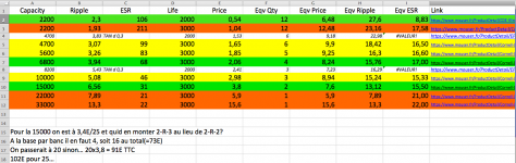
I don't know what solution you have in mind but I did spend some time re caps and bypasses. It appears in 30y the world has moved on and while my excellent Philips caps were great back then, but benefited clearly from several bypasses, it appears modern caps are far better re ESR and ESL across a large frequency band. So I might have to revise my old practices. Same for paralleling smaller caps instead of a big one, my old common practice, something I wanted to do. But I checked today's parameters and surprisingly big caps seem to be the best option (unless considering a silly number of 2200uF caps that would have to be connected anyhow)! I have attached a file that summarises my findings - may that be of some potential assistance to you.
Again many many thanks for your kind answer, very appreciated
Stay safe
Claude
PS: sadly not allowed to attach excel files here so did a screenshot. Should you be interested in the full excel file, just PM me.
Your answer is not long at all (there were many questions) and is in fact highly appreciated. Many thanks fo all your time and sharing your knowledge.
I am also glad to hear you will also build this amp, I was begin to feel lonely, so this is excellent news. May I ask you what kind of PS you are going for? Is that SMPS perhaps?
I do not intend to sell the amp but then someone else might indeed (mis)use it so I will take your point regarding Earth into consideration, eventhough France doesn't allow me easily to change plug direction. I will think about it to amend the schematic accordingly, after all, that amp will indeed have far more energy than anything else. I may also change a few other bits while at it (fuse location etc.)
I also understand that the snubber hype we ignored decades ago... might just be that: a hype.
Just as a note, the 2 bridges came only because I saw most Nelson Pass builds with it, as recommended in his papers. Believe some floating re tranny shield / ground and noise discussion. If I recall correctly in Fab's link on Grounding there is also mention of this set up. For now will skip that, but of course any other poster with amp building experience will be taken into consideration, happy to be proved wrong.
I have read meanwhile some horror stories re CLC so despite questionable efficiency on the paper I will stick safely to CRC.
I don't know what solution you have in mind but I did spend some time re caps and bypasses. It appears in 30y the world has moved on and while my excellent Philips caps were great back then, but benefited clearly from several bypasses, it appears modern caps are far better re ESR and ESL across a large frequency band. So I might have to revise my old practices. Same for paralleling smaller caps instead of a big one, my old common practice, something I wanted to do. But I checked today's parameters and surprisingly big caps seem to be the best option (unless considering a silly number of 2200uF caps that would have to be connected anyhow)! I have attached a file that summarises my findings - may that be of some potential assistance to you.
Again many many thanks for your kind answer, very appreciated
Stay safe
Claude
PS: sadly not allowed to attach excel files here so did a screenshot. Should you be interested in the full excel file, just PM me.
Attachments
Hi ClaudeG,
You've apparently been thinking down to the detail over a number of aspects of the design already. Well done. 🙂
Thanks for your alcap comparison table, indeed useful comparison.
2x15000µF show lower ESR than 6x4700µF (!) It looks like these parts are audio-grade or general purpose caps; low-ESR series could provide better performances, but would be more costly 😡.
I just checked that I went for 10000µF caps for my FSSA2😀 but you'll read below that they're not expected to do the full job alone.
About the two bridges: If advised and proposed as a better solution, then it has to be related to some effect or performance enhancement which we couldn't see from just the functional model of the circuit. As you said, maybe related to noise discussion, together with screening; we 'd need to consider the parasitic elements to account for it (?).
Supplying my FSSA2 amp: this is DIY right? It therefore involves some part of over-engineering😀....
Leading idea is to reduce as possible the effects of a "limited" PSRR of the CFA amp.
What you then want are rock-solid power voltage rails: either you go the usual route with very large XFMR + cap banks, or you could choose a SMPS, followed by a BJT ballast-regulator. The ballast is here to ensure the DC rail voltage is not altered even during sudden large current surges over a large-enough frequency band, for which the SMPS control loop would not be fast enough (its BW is typically 3--10kHz)
So I thought: single main PSU 800W +/-54V followed by one BJT ballast for each 50VDC rail, not sure yet I'd go for split supplies at this level (should not be necessary)
Thanks for sharing your concerns/thoughts and comments.
Let's enjoy DIY and make this beautiful piece of electronics sing.
Take care.
Kal.
Hi Kalamin,
You've apparently been thinking down to the detail over a number of aspects of the design already. Well done. 🙂
=> Many thanks... and yes, thinking over and over, did really my homework and didn't post to bother people from scratch. But regardless the theory I understand as an old engineer, what I really need are best practices in this league of amps. I understand the bascis for chip amps, the basics of old amps, but I can't afford to reinvent the wheel for today's best practices around top amps.
Not easy to get feedbacks apprently, but the Pass section is far more detailled so I will dig there again.
Thanks for your alcap comparison table, indeed useful comparison.
2x15000µF show lower ESR than 6x4700µF (!) It looks like these parts are audio-grade or general purpose caps; low-ESR series could provide better performances, but would be more costly 😡.
=> Thanks. I thought you would like it and as you can see by the colour codes you came to exactly the same conclusion as me. 30y ago things looked completely different!
The 15000uF caps are already low ESR caps, from a serial production though. Indeed no fancy hyper audio caps to $$, but when you compare ESR etc. you find out that the difference is thin and that you end up with a very low ESR that is enough in comparison with cables, connections etc. Plus if paralleling many of them, which I intend to do, you are better off with many of these VG caps, than with a few audio grade ones. At least on the paper and so far my findings... Experience welcome of course.
About the two bridges: If advised and proposed as a better solution,
=> I have spent the night looking into the various Pass sections, Class A mainly and some A/B. The vast majority of serious amps are using 2 bridges. Floating, grounding, found a paper by Papa on that and that's also the route with the DIYaudio PS kit. Call it perhaps pure mimetism, but that seems to be the best practice and the last thing I want is to mess with groundloops. I may follow blindly as again I don't see any difference re current rectification with 1 bridge, but well, back to the drawing board...
May save on bridges re groundbreaking on the other hand, found advise to use thermistors (CL60), seems to make sense, will dig further again in the excellently documented Pass section! All that are best practices to avoid indeed parasitic noises.
Regarding SMPS feed (and overkill LOL), I also considered this option for a long time, following all this with interest, especialy since playing with good SMPS output filters. What put me off is that at the end it cost roughly the same but is not within my reach re repairs and I don't trust long term reliability (if things go wrong the entire amp can go bang!), whereas LS is no brainer for decades. Liked though the "stiff" power supply and for sure can work greatly in bass, especialy with your ballast solution. Will follow what you do with lot of interest, be it even just from an intellectual POV!
So I thought: single main PSU 800W +/-54V followed by one BJT ballast for each 50VDC rail, not sure yet I'd go for split supplies at this level (should not be necessary)
=> I read Fab's recommandation re 800W per channel when going SMPS. I guess it is complicated to draw a line as when you dig into some Audio SMPS specs or discussing with their designers you find out that some ratings are more music power than full power all the time. 800W can easily translate into permanent 200W with 1200W provision for bursts. You may not need more though, but when designing a say a class A PS things are getting tricky. Commercial PS à la Meanwell on the other hand seem more credible provided you leave some safety margin, but then you need negative rails, split per channel, large filters to get ripple down...
Thanks again a lot for your very kind replies and all these fascinating options, that's what Audio DIY is about!
Stay safe
Claude
PS: I realise the screenprint doesnt show it all, in case you may need it, or anyone else, the 15000uF caps I refered to are
https://www.mouser.fr/ProductDetail...=sGAEpiMZZMvwFf0viD3Y3ROGmxq83YAGxJncOUCHPyY=
I managed to progress somewhat thanks to some kind helpers and greatly to the excellent Pass section. While at it, I also progressed on the grounding I had volontary neglected so far, but as Fab pointed to the document I was on anyway...
Fab, I hope I got it right, in particular in the way to connect the PS caps together and then to Ground. Have not yet digged into your manual re how to connect to boards, this is still general homework at this stage.
It is very late, it took me hours to think it all over again and I call it a day... I have a single oustanding question my brain is unable to process tonight: Ground lifter... what do you use at that kind of power levels???
I found CL60 alone (as per schematic, too leazy tonight to draw further), bridge alone, Bridge with cap, Bridge with cap and resistor... and other more complex solutions. Advice welcome!
Many thanks as ever
Claude
Attachments

Last edited:
Oh, and one thing bothers me while at it... in my search on other (recent) builds I haven't found anyone fitting the 0.1uF caps around the rectifier's diodes. Odd, they seemed good practice decades ago, even Papa recommended them, perhaps it is now not good anymore.
Further, I neither found anyone fitting C11 / C15 right after the bridge.
The latter have always confused me antway, and so more considering the bridge caps... as if I fit the rectifier's caps I will have kind of their equivalent anyway (well, half of their value which is rough ballpark anyway)! So C11/C15 make little sense to me, but then... so did 2 rectifiers!
Question: is it really "and", or is it"either", or... "none" nowadays LOL?
What is today's practice? Rectifier will be bog standard one, no super fast fancy stuff...
Many thanks!
Claude
Last edited:
Hi ClaudeG,
Just a thought.
Aren't you afraid getting a too high rectified voltage for the 50V caps?
Mains could get up to +6% above nominal 230V in FR (theoretic figure) and good practice is usually to consider +10%...
Just a thought.
Aren't you afraid getting a too high rectified voltage for the 50V caps?
Mains could get up to +6% above nominal 230V in FR (theoretic figure) and good practice is usually to consider +10%...
Ah, good point!
I probably need to look at it again since we raised the tranny secondary voltage. There is also probably an unknown due to the tranny possibly delivering more volts when running low load... argh!
Kalamin, you seem familiar with variations and these calculations... If using as recommended the 32V transformer, what calculation do you come up with for France and a toroid tranny? Am I still OK with 50V caps? If not, what tranny secondary voltage would you suggest? I live in F... and
perhaps worst one day re mains! I can see roughly from head that I am now likely to run at 48V or higher, ouch indeed!
I am not after the last 10W of power and if I rmember correctly the next voltage size re caps was clearly far more expensive and given I may need 20 of these spending silly money because of 2V is nonsense... EDIT: 63V caps are indeed silly prices and the caps I intented to use don't even exist in 63V!
I am all yours to follow your recommandations! I am not even sure now if my initial 30V where a good idea... wasn't aware mains could fluctuate that much...
Many thanks
Claude
Last edited:
Hi Claude
It is true that line voltage fluctuates. I notice at night at about 23:00 the maximum obtained. With the transfo ratio it provides proportionally less variation than on the main.
If you really want the amount of power you have stated I recommend 63VDC caps.
4x 63VDC 15000 uF for each channel is what I have in my FSSA1 prototype. They are reasonably priced.
You may over thinking it for the power supply. This is only for a sound power amplifier and not for precision instrumentation purpose. Length of wires to amplifier may kill the filtering you are trying to get at the PSU source. Layout is important though.
R4 should be on the V+ and not ground.
Fab
It is true that line voltage fluctuates. I notice at night at about 23:00 the maximum obtained. With the transfo ratio it provides proportionally less variation than on the main.
If you really want the amount of power you have stated I recommend 63VDC caps.
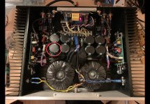
4x 63VDC 15000 uF for each channel is what I have in my FSSA1 prototype. They are reasonably priced.
You may over thinking it for the power supply. This is only for a sound power amplifier and not for precision instrumentation purpose. Length of wires to amplifier may kill the filtering you are trying to get at the PSU source. Layout is important though.
R4 should be on the V+ and not ground.
Fab
Attachments
Last edited:
Claude you might be interested in this article that describes earthing the chassis and ground lifts. That is what I do for my amps and have no issues.
If you use the CL60 instead of a 10R resistor (which I did for the USSA) I would still put a small cap (0.01uF) across the CL60.
Earthing (Grounding) Your Hi-Fi - Tricks and Techniques
Also it is my understanding that you no longer need caps across the bridge diodes if you use Quasimoto circuit at the transformer.
Hi Fab,
Many many thanks for your kind reply!
R4 on the power rail, of course,...well spotted! Work after midnight and a few cup of champ on Valentine's day, what should I expect LOL!
=> Corrected, will post schematic again.
Overengineering... neither a F1 nor a satellite nor a power station, so you are absolutely right: I am not in familiar water here LOL! Hence really appreciating you guys for real life experience and feedback, so much appreciated.
Soooo...Mains that fluctuates that much. Gosh! There are 2 solutions to that, but to chose I need more data:
A- stick to 50V caps, but then what trannny secondary voltage is dimmed safe? If someone has the result handy, it is welcome, if not, there are websites which deal with all that. More time as starting from scratch, and possible mistakes, hence asking if someone did it. And then I need to see what the resulting power would be, if acceptable.
B- go for your caps, job done. May I ask you what caps these are? I can't see it on the pix...
Apart from looking for low ESR quality caps, I had quite a problem finding caps that can handle the ripple after the rectifier... but perhaps I overengineered again as I looked for 12A ripple? The CD I mentioned come at 4$ which is dead cheap, and a pair of 15000uF ones before the R is specced at 13A ripple. So yes, there would need to be 2 before the R in the CRC... Looking forward to your caps.
Many many thanks again
Claude
Harry3, many many thanks to you: real life experience!
Now, I am not sure I get it right? Did you replace 10R with CL60 while keeping the rectifier and the 0.01uF cap? So that's RECTIFIER + CL60 + R10
Or did you use just CL60 + 100nF cap and NO RECTIFIER?
SO many variations on the same theme...
Quasimodo... well, I used one for my RIAA build (where handling power and mains fluctuations were less a problem). I went for standard values someone posted it would be fine for EVERY tranny. Now, I don't know if that is right at these power levels, but I know for sure I don't want to measure myself and lose time on this. So either std values, or no Quasimodo for me. Unless you guys tell me quasimodo is really a big plus?
I guess if quasimodo, then 2 bypass caps at the rectifier are probably not needed (those at AC)... but I would say the ones at +V and -V to tame the diodes at the output still are per definition?
More headache LOL
Thanks!
Claude
- Home
- Amplifiers
- Solid State
- FSSA amplifier build thread with review