
After some hours on it I would like to share my first impressions about Fabs FSSA-2 with you. Please note that English isn’t my first language, but I try my best not to bother you with too bad grammar.
As some may have observed I have done my own PCB for them with integrated capacitance multiplier, space for lot of capacity after the multiplier and some other footprints for bigger components. Ah – and it’s compatible to the diyaudiostore- and modushop UMS heatsink drilling pattern.
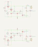
The circuit is mostly following the original schematic. Some components are touched by me:
Small resistors are mostly non-magnetic CMF55, PRP and AMRT. C1 is the Nichicon MKP-type Fab recommended some time ago. The amplifier is running from +/-48V rails - about +/-45V after the CMX.
I’ve used my personal mid-high-reference speakers consisting of the limmerhorns.de 630BC1 waveguide equipped with the stock speakers B&C 6NDL38 and the compression ring-radiator DE360. They are crossed to one Wavecor SW270BD01 per side at 300Hz. That means: Every amp that is talked about here only had to drive the upper part of the musical spectrum. The lower octaves are driven by a EV CPS2 (+/-90V EF2 with good old metal-cans, 2SC3281/2SA1302 as drivers and VFA frontend – rock solid and I really like it powering the lows). MiniDSP Flex Digi and two Topping E70 Velvet are finishing the lineup in the signal chain.

The complete setup is getting filtered power through Furman PL-conditioners because I’m living near some big steel-factorys and have to live with some nasty DC on the line and fluctuating AC during their ovens are powering.
I’ve also build the USSA-5 and that’s what I’d like to compare the FSSA-2 with most of the time. I also have two channels of VZ’s non switching output stage with “Ampliwire”-frontend (VFA) and a “Wolverine”-style OPS with “Spooky”-frontend (VFA).
The first 30 minutes are the hardest – or: let it burn for a while…
Really… I was shocked listening to the amp the first time after finishing. At that time it had only seen some sinusoidal- and squarewaves at different levels into my dummy loads and some “searching for hum” while doing the cabling through some old speakers.
So I let it play some music from local radio stations thinking about all the time that have gone during the build and what else could I have done during it… But it didn’t took that long. After about 30-45 minutes it began to change. “Was that the chunky snare I have learned to love through the USSA-5? Yeah it is!” You could call it the “Fab-snare” if you like. CFA type of feedback combined with lateral FETs in the output done by a talented designer seems to do something magic.
At this point I switched back to some higher quality sources again (FLAC or HiRes through Tidal – Electronic, Rock, Rap, Pop – Everything I’ve seen and wanted to hear in this moment). And from this point two hours gone by like a blink. The FSSA-2 is much more to my liking compared to the USSA-5. Both are great amplifiers. Don’t get me wrong. But The USSA-5 is more the gentleman: Press play and you will be served with details and smooth, flattering voices – if you want! And that’s the main point where both brothers are different. The FSSA-2 is more the Sherlock Holmes directly jumped out of the BBC-remake. Powerful, rough but letting you know every single detail - without asking if you want it that way. Straightforward upper mids and highs without getting nasty. Clear and articulated voices. I like! And it’s very talented to differentiate between single tones, instruments and sounds like synthesizer-made effects. Not the best talent of the USSA-5. I never heart my mid-high-modules that way. Very 3D-like – but that may be because the way the power supply was made, too. This time I’ve used a strictly divided dual-mono-design I haven’t done it in the amps made before.
Conclusion: A very musical amp with very good separation and an overall very musical presentation without any habit making listening stressful. Thank you Fab for this masterpiece.
As some may have observed I have done my own PCB for them with integrated capacitance multiplier, space for lot of capacity after the multiplier and some other footprints for bigger components. Ah – and it’s compatible to the diyaudiostore- and modushop UMS heatsink drilling pattern.
The circuit is mostly following the original schematic. Some components are touched by me:
- Q1/Q2 are TTC011/TTA006 for their bigger body and therefor better heat transfer to the environment
- Q3/Q4 (small CMX) are BD139/BD140 TO-126 devices for the same reason as seen before
- C9/C10/C11/C12 were replaced by Panasonic ZS 180uF/63V Hybride-Polymer because I had them here in my stash
- R29/R30 are Mundorf mResist Ultra TO247
- Highpower capacitance multiplier followed by 5000uF per rail is added to each board and rail – see schematic in the attachments
Small resistors are mostly non-magnetic CMF55, PRP and AMRT. C1 is the Nichicon MKP-type Fab recommended some time ago. The amplifier is running from +/-48V rails - about +/-45V after the CMX.
I’ve used my personal mid-high-reference speakers consisting of the limmerhorns.de 630BC1 waveguide equipped with the stock speakers B&C 6NDL38 and the compression ring-radiator DE360. They are crossed to one Wavecor SW270BD01 per side at 300Hz. That means: Every amp that is talked about here only had to drive the upper part of the musical spectrum. The lower octaves are driven by a EV CPS2 (+/-90V EF2 with good old metal-cans, 2SC3281/2SA1302 as drivers and VFA frontend – rock solid and I really like it powering the lows). MiniDSP Flex Digi and two Topping E70 Velvet are finishing the lineup in the signal chain.
The complete setup is getting filtered power through Furman PL-conditioners because I’m living near some big steel-factorys and have to live with some nasty DC on the line and fluctuating AC during their ovens are powering.
I’ve also build the USSA-5 and that’s what I’d like to compare the FSSA-2 with most of the time. I also have two channels of VZ’s non switching output stage with “Ampliwire”-frontend (VFA) and a “Wolverine”-style OPS with “Spooky”-frontend (VFA).
The first 30 minutes are the hardest – or: let it burn for a while…
Really… I was shocked listening to the amp the first time after finishing. At that time it had only seen some sinusoidal- and squarewaves at different levels into my dummy loads and some “searching for hum” while doing the cabling through some old speakers.
So I let it play some music from local radio stations thinking about all the time that have gone during the build and what else could I have done during it… But it didn’t took that long. After about 30-45 minutes it began to change. “Was that the chunky snare I have learned to love through the USSA-5? Yeah it is!” You could call it the “Fab-snare” if you like. CFA type of feedback combined with lateral FETs in the output done by a talented designer seems to do something magic.
At this point I switched back to some higher quality sources again (FLAC or HiRes through Tidal – Electronic, Rock, Rap, Pop – Everything I’ve seen and wanted to hear in this moment). And from this point two hours gone by like a blink. The FSSA-2 is much more to my liking compared to the USSA-5. Both are great amplifiers. Don’t get me wrong. But The USSA-5 is more the gentleman: Press play and you will be served with details and smooth, flattering voices – if you want! And that’s the main point where both brothers are different. The FSSA-2 is more the Sherlock Holmes directly jumped out of the BBC-remake. Powerful, rough but letting you know every single detail - without asking if you want it that way. Straightforward upper mids and highs without getting nasty. Clear and articulated voices. I like! And it’s very talented to differentiate between single tones, instruments and sounds like synthesizer-made effects. Not the best talent of the USSA-5. I never heart my mid-high-modules that way. Very 3D-like – but that may be because the way the power supply was made, too. This time I’ve used a strictly divided dual-mono-design I haven’t done it in the amps made before.
Conclusion: A very musical amp with very good separation and an overall very musical presentation without any habit making listening stressful. Thank you Fab for this masterpiece.
Attachments
Last edited:
Wonderful feedback and details about your FSSA-2 project, nfsgame!!
I would never know English was not your primary language, very well articulated 😉.
I would never know English was not your primary language, very well articulated 😉.
Hi nfsgame , thanks for your kind word but you need to take all the credits for your magnificient adaptation of the FSSA-2 amp. Indeed the FSSA class AB has more dynamics than the USSA class A but the Latter has his strength too like smoothness as you mention...So after all it is a question of synergy with the rest the system and overall a question of taste! In the end, what matters is the listening pleasure and nothing else…
note: you can upgrade the input cap also….😉
Fab
note: you can upgrade the input cap also….😉
Fab
Dear Fab,
I have some questions concerning R3A and R4A, for the sake of my better understanding only. In the manual you show measurements (simulations?) where the presence / absence of these resistors affects H2 by a quite large margin. According to the BOM, R3=R4=20R 1% whereas the parallel R3A=R4A=22k 1%.
My theoretical concern is that 20R || 22k = 19.981R which is an 0.09% difference to the nominal 20R, obviously well below the 1% tolerance of R3 and R4.
Could you please share your understanding on how such a small difference can give rise to such a remarkable change in the H2 behavior? How well shall these resistors be really matched, including the left and right channels, in order to get an identical H2 figure in stereo?
Thank you in advance,
Miklos
Dear Miklos
Matching is of no importance. Indeed the 22k value is for no adjustment (inherent H2 level of the amp) provided for H2. The value needs to be changed to a much lower value to get the change in H2. For example, it could get as low as 470 ohms. This is not linear at all like 4k7 or even 2k2 will not do any substantial change. In general, you will get more H2 without changing the 22 K ohms and reducing the value on one side will lower H2 up to a level even lower than H3. The value for a certain level will be different for each FSSA build but should be similar between left and right channels depending on the matching of the active parts used. This is for experimentation and without a THD analyses it can prove somewhat difficult to adjust to a desired target level. Maybe temporarily using a multiturn 5k potentiometer….But in the end, the nominal level of H2 is probably the optimal for my own taste….
I realize that this part may not be enough explained….
Fab
Dear Fab,
thank you for your quick and extensive reply. So my basic understanding is that the 20 Ohm source resistors for the JFETs (feedback aside) are just fine and, on top of that, we have the nice option of fine-tuning those 20 Ohms by adding the parallel resistors, if ever needed for whatever reason.
Am I then guessing right that installing the 22k resistors at R3A and R4A or leaving them out shall make no audible difference?
Thanks again,
Miklos
Dear Fab,
there is another design detail where I would be pleased to get your insight: C14/R23 and C15/R24.
At the first glance, these seem to provide some high-frequency bypass routes around the base/collector of the Q6 and Q7 driver Darlingtons, as if they were meant to protect the output stage from potential parasitic oscillations. I also understand your note that slightly changing the values of C14 and C15 results in a different sound character. My specific questions are the following:
Of course, it is all easy enough to try once I get there, I just wonder if you have played with this before and/or see any danger about it?
Thank you in advance,
Best wishes,
Miklos
there is another design detail where I would be pleased to get your insight: C14/R23 and C15/R24.
At the first glance, these seem to provide some high-frequency bypass routes around the base/collector of the Q6 and Q7 driver Darlingtons, as if they were meant to protect the output stage from potential parasitic oscillations. I also understand your note that slightly changing the values of C14 and C15 results in a different sound character. My specific questions are the following:
- Can one theoretically leave these out or is the circuit prone to oscillations without them?
- Have you, by chance, also listened to the amplifier without installing C14/R23 and C15/R24? If yes, how did that sound compare to either the 68pF or 82pF installations?
Of course, it is all easy enough to try once I get there, I just wonder if you have played with this before and/or see any danger about it?
Thank you in advance,
Best wishes,
Miklos
Miklos
You are right that the RC purpose is for frequency compensation. However, it is more a belt and suspenders feature in this low/ moderate feedback design. I was able to not install it but I have not done enough tests to have a clear recommendation. It was a long time ago and I did not A/B test unfortunately for the sound. Also for the sound, R40/R41 can be tweaked if needed giving a similar effect. If you want to tweak the sound I recommend not removing the RC but rather playing with R40/41 values - but not higher than the one listed.
Fab
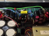
Here is my FSSA amp using Alfet with 35vac toroidal paired with Prasi LT4230 CRC psu board. Made a chassis with available sinks that I had but runs a bit hot after an hour of playing.


Manniraj,
Congratulations on completing the build.
However, the heat sink fins are horizontally oriented - probably that is why you are experiencing the heat; the hot air cannot move upwards as efficiently as with a heat sink with vertically oriented fins.
Congratulations on completing the build.
However, the heat sink fins are horizontally oriented - probably that is why you are experiencing the heat; the hot air cannot move upwards as efficiently as with a heat sink with vertically oriented fins.
That is true but I had these spare and thought of using them considering the expensive chassis that we need to spare now a days with shipping and other things. I will try to add a small fan to see if it helps in cooling it down.However, the heat sink fins are horizontally oriented - probably that is why you are experiencing the heat; the hot air cannot move upwards as efficiently as with a heat sink with vertically oriented fins.
Thanks
Thanks Claude,Well done!!!
I am soooo late on my build, you guys are amazingly fast!
Let us know how you like it
Claude
Initial impressions are very good and I will give some time to settle and pair with passive preamp without any gain as well. Right now using HPA1 clone as preamp.
Thanks
- Home
- Amplifiers
- Solid State
- FSSA amplifier build thread with review