A major difference between positive current feedback (PCF) and Hawksford Error Correction (HEC) is that PCF shouldn't change the harmonic structure of the amplifier, whereas HEC attempts to remove all differences between the output and the input (multiplied by the closed loop gain), including the harmonics. I need to run some simulations to verify this conjecture. If anyone is really interested, I can provide the systems of circuit equations used to produce all of the resistor ratios shown in the circuit diagrams.
Hello lhquam. Please count me in. Thank you.
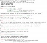
Hello lhquam. Consider the model Op Amp with diff inputs which is the top right view of your post.
1. Let B=1 with an Rint = 0.2 Ohms.
2. Let A = 21
3. Let Rsense =0.2 Ohms.
I hope the following are the correct answers after solving the equations you showed.
a} Rfn/Rfs=[A-1]/2 = 10
b} Rfp/Rf1 = A/2 = 10.5
c} CLG =21
1. Let B=1 with an Rint = 0.2 Ohms.
2. Let A = 21
3. Let Rsense =0.2 Ohms.
I hope the following are the correct answers after solving the equations you showed.
a} Rfn/Rfs=[A-1]/2 = 10
b} Rfp/Rf1 = A/2 = 10.5
c} CLG =21
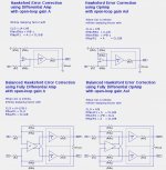
I discovered a error in the bottom left circuit diagram in post #698 http://www.diyaudio.com/forums/pass-labs/275921-first-watt-f7-review-70.html#post4757023. Here is the corrected set of HEC circuit diagrams:
Attachments
Hello lhquam. Consider the model Op Amp with diff inputs which is the top right view of your post.
1. Let B=1 with an Rint = 0.2 Ohms.
2. Let A = 21
3. Let Rsense =0.2 Ohms.
I hope the following are the correct answers after solving the equations you showed.
a} Rfn/Rfs=[A-1]/2 = 10
b} Rfp/Rf1 = A/2 = 10.5
c} CLG =21
and Rlfbn/Rfbs = 20. Yup that is right.
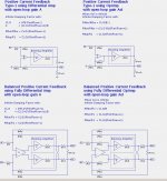
Here is the derivation of the feedback resistor values for the Positive Current Feedback implementation using a differential amplifier with gain A. To make the algebraic equations more readable, the resistor names have been shortened to two characters. What I show is the output from Maxima, a symbolic algebra manipulation system. Sorry, but I haven't figured out a good way to place all of this in a single pdf file.
Attachments


Hello lhquam. The left view shows that the ratio of the resistors are exactly equal; unlike the difference of [10 versus 10.5] I calculated in the earlier example. Please explain.
Thanks for the derivation of the results.
Thanks for the derivation of the results.
Hello lhquam. The left view shows that the ratio of the resistors are exactly equal; unlike the difference of [10 versus 10.5] I calculated in the earlier example. Please explain.
Thanks for the derivation of the results.
The difference will be explained when I show the circuit equations and analysis for the PCF using an opamp with infinite gain vs. a fixed gain differential amplifier. Basically, the opamp in+ node has 2 resistors vs. the in- node has 3 resistors, resulting in an asymmetry.
The difference will be explained when I show the circuit equations and analysis for the PCF using an opamp with infinite gain vs. a fixed gain differential amplifier. Basically, the opamp in+ node has 2 resistors vs. the in- node has 3 resistors, resulting in an asymmetry.
Thanks lhquam for your clear reply. Please refer to the schematic in post 705.
1. If A = 200 and B = 1 which are conditions like found in a commercial Class AB amp, then the calculated value of CLG which you show is unusually high when using Rint [of power buffer B] = the value of the external Rsens. In practice, CLG can be expected to be ~22
2. Suppose the resistor to the non-inverting input is grounded, and the music signal is offered instead to the resistor feeding the inverting input. Is the resultant amp stable, and does it utilize PCF?
Best regards
The "Commercial Class AB" amplifier should be considered as self contained block which includes its own feedback loop(s), since we are not modifying the guts of the amplifier. Thus, reasonable values for A might be around 20X. Reconnecting the signal input from the non-inverting to the inverting input would completely change the circuit equations and all of the results.
Antoinel: I need to correct my last response. The value of B in the PCF or HEC circuit should equal the voltage gain of the "Commercial Amplifier". The value of A should probably be between 2 and 3. The value of Rint can be determined from measurements under different resistive loads.
Antoinel: I need to correct my last response. The value of B in the PCF or HEC circuit should equal the voltage gain of the "Commercial Amplifier". The value of A should probably be between 2 and 3. The value of Rint can be determined from measurements under different resistive loads.
Thanks lhquam. Unit B in your schematic is a [respectable] power amp which has a non-inverting input, and a power output which are accessible to the user. This power amp also has an overall negative feedback [ ONF] loop [or maybe not] which is not available to the user. The ONF components are not shown in your schematic because they are part and parcel of unit B.
.
1. The damping factor declared by the supplier of the power amp [unit B] gives the value of Rint which then allows to chose Rsense.
2. The voltage gain of this power amp [unit B] is also declared and maybe = 21.
3. Unit A in your schematic is a preamp which has differential inputs and a voltage gain of 2-3.
4. Units A and B plus the associated and additional input and feedback resistors then constitute a new amp which has the performance you declared by its equations.
So by example, take diyF6 to be unit B. Unit A maybe diyBA3 front end tailored to have a gain of 2. The complementary input JFETs in diyBA3 front end or in the so called diyLSK preamp ..is the part of this diff amp in unit A where PCF and ONF terminate.
Antoinel:
Your interpretation in points 1-4 seem to be correct. I consider the preamp with associated resistors to be the PCF (or HEC) circuit, which when wrapped around the amplifier (characterized by voltage gain B and internal resistance Rint) constitutes and new amplifier as you described on point B. The preamp or front-end can be anything from a suitably modified BA3GS (BA-3 Gain Stage) to a DIY board containing an OpAmp or some other differential amplifier.
The solutions to the circuit equations I presented are designed to have no additional overall negative feedback. That is, the presence or absence of the Rfbp and Rfbn PCF feedback resistors to not change the output in the condition when there is no output load.
The design process for the fixed-gain A differential amplifier is as follows:
- Determine B and Rint for the amplifier to be used.
- Pick Rsen, R1, and Rfbs.
- Choose a desired CLG.
- Compute A, Rfbn/Rfbs and Rfbp/R1
What remains to be understood is the stability of these feedback schemes when the underlying amplifier has phase lag. Cordell's "Designing Audio Power Amplifiers" has some discussion of feedback compensation for some HEC implementations but I have not done the needed analysis for my PCF and HEC circuits.
My experience is that intrinsic bandwidth limits are exaggerated by PFC,
so that high frequency roll-offs will occur earlier. Not much of a stability issue,
because the phase lag tends to move the feedback away from positive phase,
but worth noting.
You do have to watch simpler stability issues related to source impedance
and/or and load values. High source impedance, or a load comparable to the
sense resistor can be invitations to problems.
😎
Thanks lhquam for your clear reply. Please refer to the schematic in post 705.
1. ...
2. Suppose the resistor to the non-inverting input is grounded, and the music signal is offered instead to the resistor feeding the inverting input. Is the resultant amp stable, and does it utilize PCF?
Best regards
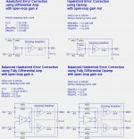
I analyzed the circuit equations with the signal input to the inverted input of the opamp and got the following resistor values:
Rlfbn/Rfbs=CLG/B
Rfbn/Rfbs=CLG/(Rint/Rsen+1)
Rfbp/R1=(B+CLG)/(Rint/Rsen+1)
I also ran a simulation and everything looks good, including the nearly infinite damping factor. Rfbn/Rfbs=CLG/(Rint/Rsen+1)
Rfbp/R1=(B+CLG)/(Rint/Rsen+1)
I will soon show some simulation results for HEC and PCF using opamps and a IRFP240/IRFP9240 output stage.
I analyzed the circuit equations with the signal input to the inverted input of the opamp and got the following resistor values:
Rlfbn/Rfbs=CLG/BI also ran a simulation and everything looks good, including the nearly infinite damping factor.
Rfbn/Rfbs=CLG/(Rint/Rsen+1)
Rfbp/R1=(B+CLG)/(Rint/Rsen+1)
I will soon show some simulation results for HEC and PCF using opamps and a IRFP240/IRFP9240 output stage.
Hello lhquam. It is most interesting that your circuits, and their simulations are broadly versatile. I look forward to your upcoming simulations.
I'll just leave this right here: First Watt F7 Stereo Power Amplifier | The Absolute Sound
Gracias!!!🙂
- Home
- Amplifiers
- Pass Labs
- First Watt F7 review