Here is an elaboration and simulation of the PCF-T1-opamp circuit shown in post 713.
Thanks as always.
I believe your explorations clearly show that I opened a can of worms....
😀


It is interesting that Disck Olsher compared the F7 to the F3. I own a pair of BassZillas Platinum Edition MKII and wasn't sure if the F3 could drive them to play at a reasonable volume. After reading his review, I have added the F3 to my project wish list.
Let me know if you're moving on from 'wish' to 'build'. I've some PCBs here somewhere... and a few of the LU parts.
Hello lhquam. Your pdf is easy to follow and to understand its calculation methodology. I have this question using the general schematic therein.
What is the magnitude of [u-v]; which is the voltage difference at the inputs of its diff amp relative to [u-v]' of the diff amp in a classical power amp of similar CLG?
Thank you
What is the magnitude of [u-v]; which is the voltage difference at the inputs of its diff amp relative to [u-v]' of the diff amp in a classical power amp of similar CLG?
Thank you
Hello lhquam. Your pdf is easy to follow and to understand its calculation methodology. I have this question using the general schematic therein.
What is the magnitude of [u-v]; which is the voltage difference at the inputs of its diff amp relative to [u-v]' of the diff amp in a classical power amp of similar CLG?
Thank you
There is little difference in the analysis between using an opamp vs. a diffamp other than that an opamp usually has a very high open-loop gain.
A good approximation which ignores the signal loss due to Rsen is as follows: If you look at the equations, w = Aol*(u-v), thus u-v = w/Aol. When the feedback factor w around the existing amplifier is considered, w/x = CLG/(W*B), thus u-v = x*CLG/(W*B).
I will be showing another example using a UGS front-end stage instead of an opamp.
Hello lhquam. My hand calculations using the data for the simulation amp [in pdf] show that PCF plus NFB unbalances the front end differential amp of its opamp [u-v] more than by using NFB only. Is this true?
Explain what you mean by "unbalances".Hello lhquam. My hand calculations using the data for the simulation amp [in pdf] show that PCF plus NFB unbalances the front end differential amp of its opamp [u-v] more than by using NFB only. Is this true?
Explain what you mean by "unbalances".
1. I calculated [u-v] for the simulation amp = 0.008 V by assuming Vout or [y] = 8 V. The CLG = 6 gave a value for Vin or [x]=1.333 V.
2. I mentally removed the positive feedback resistor 227K; but I kept Vin or [x] or =1.333 V.
3. The value of K before and after removing the 227 K resistor is still = 4.
4. The new CLG of the simulation amp without PCF equals K +1 for a non-inverting amp = 5. The new value of Vout or [y] = 6.665 V.
5. The calculated new [u-v]'= 0.006 V.
6. The difference {[u-v] - [u-v]'} =0.002 V. This relative increase in [u-v] in favor of the simulation amp is what I meant by "unbalances more" its front end differential amp of the opamp.
In order to remove the effects of PCF, the positive feedback resistor Rfbp is removed and the (global) negative feedback resistor Rfbn must modified to maintain the value of K. Rfbn is playing a dual role in being the differential counterpart to Rfbp, and in controling negative feedback around the "existing amplifier". When K=1, Rfbn only acts as the differential partner in PCF.
In most cases, one would use this PCF circuit with K=1, leaving the harmonic structure of the existing amplifier alone, and only controlling the damping factor.
Actually these is a better way to think about the removal of the PCF. When the denominator of Rp in equation %o52 is zero, Rfbp is infinite and there is no positive feedback. This occurs when Rout = (Rint+Rsen)/K. Plug this value for Rout into the equations and you get:
Rln=(1-K+CLG*K)/(B-(CLG*K)/Aol)-1
Rn=((1/Aol+1)*CLG*K-B)/(K-1)-1
Rp=infinity
when K=1
Rln=-((Aol+1)*CLG-Aol*B)/(CLG-Aol*B)
Rn=infinity
Rp=infinity
Rln=(1-K+CLG*K)/(B-(CLG*K)/Aol)-1
Rn=((1/Aol+1)*CLG*K-B)/(K-1)-1
Rp=infinity
when K=1
Rln=-((Aol+1)*CLG-Aol*B)/(CLG-Aol*B)
Rn=infinity
Rp=infinity
Hello lhquam. Thank you for your reply and the above equations. I am searching for evidence in your equations; like the magnitude of [u-v] which can shed light on the mechanism at play for PCF+NFB versus its NFB control. There's got to be a state which differentiates between the two amps.
Hello lhquam. Thank you for your reply and the above equations. I am searching for evidence in your equations; like the magnitude of [u-v] which can shed light on the mechanism at play for PCF+NFB versus its NFB control. There's got to be a state which differentiates between the two amps.
I do not know of any particular significance to the magnitude of u-v other than its relationship to the open-loop gain of amplifier chain.
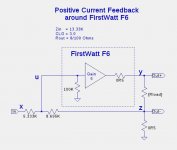
Here is the PCF circuit that Nelson might have had in mind back in an earlier post. It couldn't be simpler, but it does have some limitations such as reducing the closed-loop gain and requiring an amplifier with a gain of at least 3.
Shown is a PCF circuit for the FirstWatt F6. It reduces the closed-loop gain to 3.
Be sure to look at the pdf file.
Shown is a PCF circuit for the FirstWatt F6. It reduces the closed-loop gain to 3.
Be sure to look at the pdf file.
Attachments
Let me know if you're moving on from 'wish' to 'build'. I've some PCBs here somewhere... and a few of the LU parts.
I am putting the finishing touches on two cases I made using Conrad heat sinks. One is for the M2, which is still in the "frankenstein" chassis I use for testing, the other is for the F6. I need to finish them first before committing to other projects.
Thanks for the offer, I'll let you know when I am ready to proceed.
Here is the PCF circuit that Nelson might have had in mind back in an earlier post. It couldn't be simpler, but it does have some limitations such as reducing the closed-loop gain and requiring an amplifier with a gain of at least 3.
Shown is a PCF circuit for the FirstWatt F6. It reduces the closed-loop gain to 3.
Be sure to look at the pdf file.
Hello and thank you lhquam. Will the calculations in this pdf apply equally to the Class AB variant of diyF6?
Hello and thank you lhquam. Will the calculations in this pdf apply equally to the Class AB variant of diyF6?
The damping-factor (and thus Rint) of a Class-AB amplifier often changes with power level, so the resulting amplifier Rout will be be constant. Otherwise the PCF should be fine if the amplifier parameters are realistic.
The damping-factor (and thus Rint) of a Class-AB amplifier often changes with power level, so the resulting amplifier Rout will be be constant. Otherwise the PCF should be fine if the amplifier parameters are realistic.
Thanks lhquam.
- Home
- Amplifiers
- Pass Labs
- First Watt F7 review