I am putting the finishing touches on two cases I made using Conrad heat sinks. One is for the M2, which is still in the "frankenstein" chassis I use for testing, the other is for the F6. I need to finish them first before committing to other projects.
Thanks for the offer, I'll let you know when I am ready to proceed.
No worries.🙂
I just saw a significant typo in my previous message. It should have said:The damping-factor (and thus Rint) of a Class-AB amplifier often changes with power level, so the resulting amplifier Rout will be be constant. Otherwise the PCF should be fine if the amplifier parameters are realistic.
The damping-factor (and thus Rint) of a Class-AB amplifier often changes with power level, so the resulting amplifier Rout will not be constant.
To clarify matters, the PCF circuits shown in post #713 http://www.diyaudio.com/forums/pass-labs/275921-first-watt-f7-review-72.html#post4760110 were not intended to advocate the use of opamps in an actual amplifier build. Opamps were used because of their simple circuit equations, making it possible to derive relatively simple equations for the PCF circuits. I have also experimented with circuits using a UGS style front end in place of the opamp and a source-follower output stage. The PCF behavior is defined by the same equations as in post #713, but I am still working to get a better handle on the circuit harmonics and phase relationships.
Hello lhquam. The use of Op Amps [like NE5532 etc] broadens the utility scope of your designs; which is valuable.To clarify matters, the PCF circuits shown in post #713 http://www.diyaudio.com/forums/pass-labs/275921-first-watt-f7-review-72.html#post4760110 were not intended to advocate the use of opamps in an actual amplifier build. Opamps were used because of their simple circuit equations, making it possible to derive relatively simple equations for the PCF circuits. I have also experimented with circuits using a UGS style front end in place of the opamp and a source-follower output stage. The PCF behavior is defined by the same equations as in post #713, but I am still working to get a better handle on the circuit harmonics and phase relationships.
Most excellent. In what appears appears to be your copious free time, you
might want to take a look at the inverting amplifier case as well, as I found
it the simplest.
😎
I finally got around to considering the inverted case. Yes, it has 2 fewer resistors and very simple equations.
Attachments

I finally got around to considering the inverted case. Yes, it has 2 fewer resistors and very simple equations.
Hello lhquam.
What is the relative signal phase at the inputs [u and v]. These signals seem to me to be 180 degrees out of phase, and thus problematic.
Hello lhquam.
What is the relative signal phase at the inputs [u and v]. These signals seem to me to be 180 degrees out of phase, and thus problematic.
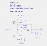
Look at the opamp input polarity. The input X goes to the opamp negative input, and the polarities get flipped. U = -((1+CLG)*X)/(gm*Rload) V = -X/(gm*Rload) The negative feedback factor is NFB = (gm*Rload)/CLG
Look at the opamp input polarity. The input X goes to the opamp negative input, and the polarities get flipped. U = -((1+CLG)*X)/(gm*Rload) V = -X/(gm*Rload) The negative feedback factor is NFB = (gm*Rload)/CLG
Thanks lhquam. Maybe you and/or the software that you are using can populate the schematic with sine wave symbols for a comparative visual.
Thanks lhquam. Maybe you and/or the software that you are using can populate the schematic with sine wave symbols for a comparative visual.
Just enter the circuit into LTSpice and run a simulation. It shouldn't be that hard.
Just enter the circuit into LTSpice and run a simulation. It shouldn't be that hard.
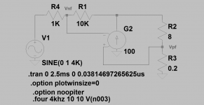
Great advice, and not hard at all; provided I got the commands right in the attached asc file. U and V signals are in phase, but LTspice finds their numerical difference [U-V] to be quite large.
Attachments
Hello lhquam.
The asc file of your attached model schematic shows that at least a Gm =100 is needed to minimize the numerical difference [Vpf-Vnf], and have both feedback signals in phase. I have minimized the aforementioned difference because both signals are presented to the front end differential amp [of the power amp] and are normally almost equal in magnitude. But; it may be possible that the deliberate application of PCF dictates that a certain minimum difference exist. This is done [in the attached asc file] by decreasing the value of Gm to the desired difference [Vpf-Vnf].
The asc file of your attached model schematic shows that at least a Gm =100 is needed to minimize the numerical difference [Vpf-Vnf], and have both feedback signals in phase. I have minimized the aforementioned difference because both signals are presented to the front end differential amp [of the power amp] and are normally almost equal in magnitude. But; it may be possible that the deliberate application of PCF dictates that a certain minimum difference exist. This is done [in the attached asc file] by decreasing the value of Gm to the desired difference [Vpf-Vnf].
Attachments
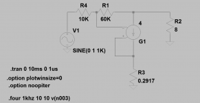
Here is a simulation of the PCF Type 2 Inverted circuit. You can play around with the circuit parameters such as gm, CLG, R1. The calculations for Rfbn and Rsen create a infinite damping factor, i.e. Rout is zero. The waveforms show a realistic example with gm=4 and CLG=6. With Rload=8, the open-loop gain is 32.
Thanks lhquam.
What does the simulation show? That circuit would be equivalent to tying all 3 of the ground points (including the input ground) together and moving the ground point to the top of the sense resistor.Hello lhquam.
Is the attached schematic viable and/or has potential? Practically, the 8 Ohm load is a reactive loudspeaker coil. The 0.2917 resistor still senses load current.
Catching up late...
...seems to have quieted down since August... BUT, the thing that interests me most is one of the graphs on page 9 of the pdf http://www.firstwatt.com/pdf/prod_f7_man.pdf.
As noted before the current sense thing has been done before.
At least one speaker mfr did this as part of their design maybe 50-60 years back.
Lynn, thanks for all the analysis, I'll be looking at that after I print some of the pages!
_-_-bear
>At least one speaker mfr did this as part of their design maybe
>50-60 years back.
About 60 years as I recall.
Interestingly, if you do this stuff with amplifiers using output transformers,
as they were, you get lots of artifacts you might not like due to the limited
bandwidth, and this is possibly why it did not gain in popularity back then.
It would have been interesting if it had been explored around the time of the
"acoustic suspension" designs direct coupled to solid state output stages.
I recall that my first Nelson Pass DIY project was a rebuild of my then loudspeakers, the Dayton Wright XG8's. This included a feedback loop from the step-up transformer secondary back to the power amp input though an opamp. The project wasn't published. You had to call Threshold and request a copy. It worked very well indeed.
Graeme
Graeme
Yet another PCF topology
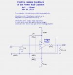
Here is an interesting PCF topology that avoids disturbing the input path to the amplifier by generating a PCF feedback current that is of the opposite phase of that generated by having a sense resistor in the path of the amplifier load as in the Type-1 and Type-2 typologies that I have previously described. This topology assumes that the V+ and V- power rails have equal opposite voltages. A sense resistor is placed in the path between each rail and the output stage. The figure on the left shows show the load current feedback is generated by summing the voltages on the amplifier end of the sense resistors. The figure on the right shows the analysis of the complete feedback circuit and how to compute the resistor values.
Here is an interesting PCF topology that avoids disturbing the input path to the amplifier by generating a PCF feedback current that is of the opposite phase of that generated by having a sense resistor in the path of the amplifier load as in the Type-1 and Type-2 typologies that I have previously described. This topology assumes that the V+ and V- power rails have equal opposite voltages. A sense resistor is placed in the path between each rail and the output stage. The figure on the left shows show the load current feedback is generated by summing the voltages on the amplifier end of the sense resistors. The figure on the right shows the analysis of the complete feedback circuit and how to compute the resistor values.
Attachments
- Home
- Amplifiers
- Pass Labs
- First Watt F7 review