Sorry… still using the reMarkable 2. It is a pricey little thing. It reminds me of how the price of real estate has gone up. Try buying one of the pyramids today… even the small one. And then there’s the cost of airlifting the thing from Egypt to take an orbit around the earth. I can’t see the profit! Fortunately for me the price of spam hasn’t gone up.
My earlier presentation focused on the inability of FFT and THD measurements to identify non-linear non-harmonic spectral components generated from non-linear transfer curves. This was specific to a 3rd harmonic component being proportionately connected to a fundamental frequency component on the output, both being exponentially related to the input sinusoid. This phenomenon can be further examined in relation to the 2nd harmonic being proportionately connected to a DC component, whereupon both are also exponentially related to the input. In this case, when an amplifying device contains a vessel to store electrons, such as a capacitor, the output can exhibit “memory type distortion”.
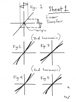
Non-linear transfer functions can take one of four basic types. These are shown in Sheet 1.
Figure 2- expansion up and down (generates 3rd harmonic)
Figure 3 - compression up and down (generates 3rd harmonic)
Figure 4 - expansion up, compression down (2nd harmonic)
Figure 5 - compression up, expansion down (2nd harmonic)
Sheet 2 shows the distortion waveforms resulting from an input sine impacted by the corresponding non-linear curves in Sheet 1. In all cases the isolated distortion waveform passes horizontally through the origin. If the input stimulus is considered to be made up of an infinite number of points with infinitely small time intervals the slope of the linear and curved transfer functions match each other in the interval between t0 (time 0) to t1 (the next time increment). Once the slope of the non-linear and linear transfer functions match there is no distortion, hence the distortion component alone must begin having zero slope or passing horizontally through the origin from t0 to t1. This also occurs for every half cycle.
The distortion waveforms show that the position of these waveform is not arbitrarily located, rather always smoothly (horizontally) connected between any sine stimulus regardless of being a half cycle, first cycle, last cycle, or any other cycle. Given a perfect amplifying device that is only affected by a non-linear transfer function there is no vessel of memory from any one point to the next point, regardless of being infinitely small. Hence for memory type distortion to occur requires a vessel to hold electrons and that the change in charge and discharge is disproportionate to the input stimulus.
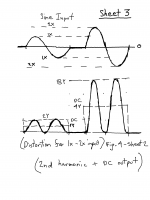
Figure 1 on Sheet 3 shows two sine inputs at 1x and 2x separated by 0x. For the transfer functions depicted in Figure 4 on Sheet 1, the 2nd harmonic changes exponentially at a 4x rate to that of an input sine changing at a 2x rate. Given the single sided nature of the distortion waveform the 2nd harmonic can be observed as reflecting a DC component changing proportionately with the 2nd harmonic, yet exponentially to the input stimulus. Hence this form of transfer function generates a non-linear DC spectrum component under circumstances of a changing input amplitude.
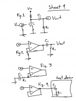
For “first cycle” or “memory type distortion” to exist requires that a vessel exists to contain electrons, and that such vessel charges and discharges those electrons in a non-linear way. Capacitor C1 in figures 1 through 4 on Sheet 4 is a vessel that can cause such memory distortion if the transfer functions of the amplifying devices take the form producing 2nd harmonics. In all cases both linear and non-linear DC components accumulate across capacitor C1. It should be noted that memory type distortion occurs for every level change of sine input, not just from zero input to the first cycle, and that this distortion is affected by the R1/C1 time constant being of variant affect by frequency and amplitude changes of the sine input. For this reason the phenomenon is considered an artifact of modulation that by any other name is still that.
My earlier presentation focused on the inability of FFT and THD measurements to identify non-linear non-harmonic spectral components generated from non-linear transfer curves. This was specific to a 3rd harmonic component being proportionately connected to a fundamental frequency component on the output, both being exponentially related to the input sinusoid. This phenomenon can be further examined in relation to the 2nd harmonic being proportionately connected to a DC component, whereupon both are also exponentially related to the input. In this case, when an amplifying device contains a vessel to store electrons, such as a capacitor, the output can exhibit “memory type distortion”.
Non-linear transfer functions can take one of four basic types. These are shown in Sheet 1.
Figure 2- expansion up and down (generates 3rd harmonic)
Figure 3 - compression up and down (generates 3rd harmonic)
Figure 4 - expansion up, compression down (2nd harmonic)
Figure 5 - compression up, expansion down (2nd harmonic)
Sheet 2 shows the distortion waveforms resulting from an input sine impacted by the corresponding non-linear curves in Sheet 1. In all cases the isolated distortion waveform passes horizontally through the origin. If the input stimulus is considered to be made up of an infinite number of points with infinitely small time intervals the slope of the linear and curved transfer functions match each other in the interval between t0 (time 0) to t1 (the next time increment). Once the slope of the non-linear and linear transfer functions match there is no distortion, hence the distortion component alone must begin having zero slope or passing horizontally through the origin from t0 to t1. This also occurs for every half cycle.
The distortion waveforms show that the position of these waveform is not arbitrarily located, rather always smoothly (horizontally) connected between any sine stimulus regardless of being a half cycle, first cycle, last cycle, or any other cycle. Given a perfect amplifying device that is only affected by a non-linear transfer function there is no vessel of memory from any one point to the next point, regardless of being infinitely small. Hence for memory type distortion to occur requires a vessel to hold electrons and that the change in charge and discharge is disproportionate to the input stimulus.
Figure 1 on Sheet 3 shows two sine inputs at 1x and 2x separated by 0x. For the transfer functions depicted in Figure 4 on Sheet 1, the 2nd harmonic changes exponentially at a 4x rate to that of an input sine changing at a 2x rate. Given the single sided nature of the distortion waveform the 2nd harmonic can be observed as reflecting a DC component changing proportionately with the 2nd harmonic, yet exponentially to the input stimulus. Hence this form of transfer function generates a non-linear DC spectrum component under circumstances of a changing input amplitude.
For “first cycle” or “memory type distortion” to exist requires that a vessel exists to contain electrons, and that such vessel charges and discharges those electrons in a non-linear way. Capacitor C1 in figures 1 through 4 on Sheet 4 is a vessel that can cause such memory distortion if the transfer functions of the amplifying devices take the form producing 2nd harmonics. In all cases both linear and non-linear DC components accumulate across capacitor C1. It should be noted that memory type distortion occurs for every level change of sine input, not just from zero input to the first cycle, and that this distortion is affected by the R1/C1 time constant being of variant affect by frequency and amplitude changes of the sine input. For this reason the phenomenon is considered an artifact of modulation that by any other name is still that.
Attachments


I have the original reMarkable. Nifty little thing, only wish the software was a bit more professional. But you can't have it all I guess.
To your post. Well reasoned, and the overview is valuable. What I have trouble with is your use of memory distortion. It is not clear to me what that actually is. Of course capacitors can take up charge and give it out at a later point, but that is normally called phase shift.
I remember the discussions on memory distortion at the end of last century, especially by Mr. Hiraga and his disciples at L'Audiophile. If I understood that correctly it was more along the lines that the operating conditions of a circuit are modified by a (strong) signal, and that subsequently the signal is processed at a different operating point than before. The circuit sort of remembers what had gone on before, hence the term memory distortion.
But that is not what you mean, isn't it?
Jan
No intend to be mischievous! I'm just trying to get some idea on what your opinion is based.
As I said, personal preference is OK, but I am always on the lookout for views backed up by facts and figures.
I mean, 200kHz - great. But why not 150kHz? Or maybe 225kHz?
Jan
Until there were high-speed op amps, almost all industrial crossovers used op amps such as the TL072 (SR = 16), as well as the NE5532 (SR = 8). Replacing op-amps in them with faster ones gives a noticeable increase in sound quality.
In fact, it is not SR that is important, but SR per 1 V of the output voltage, that is, the normalized SR.
If we consider that the peak voltage in crossovers rarely exceeds 5 V, then the normalized SR for the TL072 will be:
16/5 = 3.2 1/μs
According to the latest data, judging by the discussions on the forums, the minimum slew rate of the op-amp for use in audio amplifiers must be at least 50 V / μs, while the normalized slew rate will be 10 1 / μs.
Now let's take a typical power amplifier with an output voltage of 30 V peak.
Then taking a modest value of the reduced slew rate equal to 3.2 1/μs and multiplying it by 30 V we get SR = 96 V/μs.
From this SR value, it is easy to calculate the minimum apparent power bandwidth:
fm = SR/(2πUm) = 96/30*6,28 = 0,5 MHz = 500 kHz
Slew rate calculations - how much do I need?
John Curl:
«I have never designed an amp in the last 30 years with a slew rate of under 100V/us and I never will. It is just too compromising of the rest of the design. Early 70's amps had slew rates of about 10-25V/us for the most part and they really sounded lousy. The first amp that I listened to in my own system, that really stood out, was the Otala power amp, which has 100V/us. I still have one today, in my office, and it still sounds great.»
Until there were high-speed op amps, almost all industrial crossovers used op amps such as the TL072 (SR = 16), as well as the NE5532 (SR = 8). Replacing op-amps in them with faster ones gives a noticeable increase in sound quality.
Oh c'mon, stop taking things out of context and then try and use them to your advantage, it is insulting to the intelligence of the folks commenting in (and reading) this topic, please stick to verifiable facts, not hearsay and subjective observations.
in the attached link you can see how to generate any waveform
Epicycles, complex Fourier series and Homer Simpson's orbit - YouTube
Stuart
Epicycles, complex Fourier series and Homer Simpson's orbit - YouTube
Stuart
To your post. Well reasoned, and the overview is valuable. What I have trouble with is your use of memory distortion. It is not clear to me what that actually is. Of course capacitors can take up charge and give it out at a later point, but that is normally called phase shift.
I remember the discussions on memory distortion at the end of last century, especially by Mr. Hiraga and his disciples at L'Audiophile. If I understood that correctly it was more along the lines that the operating conditions of a circuit are modified by a (strong) signal, and that subsequently the signal is processed at a different operating point than before. The circuit sort of remembers what had gone on before, hence the term memory distortion.
But that is not what you mean, isn't it?
Jan
Thanks Jan,
To your point the term “memory distortion” is considered incorrect, rather that it is better described as “distortion memory”, whereupon capacitor C1 “memorizes” the non-linear DC distortion component un-knowingly imposed upon it as following normal R/C conditions. This includes phase shift.
My intent was to indicate that the degree of charge on C1 for any fixed input level reflects both proportionate (normal DC gain) and disproportionate (exponential) DC values that result from a non-linear transfer. The extent that distortion is completely “memorized” could be considered occurring over 5 time constants of R1/C1 taking place for any step change of input sine being held in the repetition to complete that memorization. In other words the “first cycle”, as beginning from an off condition, is only a special case. The other factor is that the R/C time constant involved as memorizing the distortion is not directly related to the frequency of the “first cycle”. This is to conclude that although using a “first cycle” stimulus can reveal distortion artifacts it does not follow that the first cycle is unique in causing such revelation, this as opposed to using conventional methods such as modulation.
Gerrit
One thing I forgot to mention Jan is that the implications surrounding the creation of non-linear DC can be far reaching, as perhaps the primary contributor to poor sound quality. This is thought essential for high frequency artifacts to fold down into the audio band.
What I wonder is the following. Music waveforms are highly a-symmetric. In that sense, they resemble some of the combined waveforms you showed on the reMarkable, in that their DC level continuously vary.
If that is the case, 'memory distortion' is a property of any music signal even if there's no amp involved.
How to reconcile that?
Jan
If that is the case, 'memory distortion' is a property of any music signal even if there's no amp involved.
How to reconcile that?
Jan
As for the normalized SR for TL072, I was wrong, I had to take a voltage of about 12.5 V, not 5 V. Then SRnorm = 16 / 12.5 = 1.3 1 / us
Jan, what about the filter? or DAC for digital signal processing. As a last resort, give the parameters, I will select a ready-made one similar in parameters or develop
Jan, what about the filter? or DAC for digital signal processing. As a last resort, give the parameters, I will select a ready-made one similar in parameters or develop
Ssassen, if for you the statements of John Curl are rumors and not verified facts, then who can I refer to to convince you and those like you? Earlier I referred to the book of Jiri Dostal, but it turns out that it is not held in high esteem by anyone, the calculations given in it also did not convince anyone of those present.Oh c'mon, stop taking things out of context and then try and use them to your advantage, it is insulting to the intelligence of the folks commenting in (and reading) this topic, please stick to verifiable facts, not hearsay and subjective observations.
petr,
You are not entirely wrong, nor entirely right. However, IMHO you are on the wrong path. Sims and waveform approximations can only get you so far. You need to pick a good topology then start on physical experimental work to find out what else matters and just how much real waveforms look like 'first cycle' waveforms. The closest one can expect to come to such waveforms in the real world is in dac output stages. By the time signals get to a power amp any sharp rate of change discontinuities such as 'first cycle' corners should be rounded out by appropriate filtering.
Also, since you mentioned John Curl, I will tell you that John calls me a few times a week to talk about all sorts of things, including sometimes about power amplifier design. Another professional amp designer, Jam, recently departed from designing at Pass Labs is usually involved in the talks too. What those guys say about slew rate is that you need enough of it, but more than that is not necessary and may hurt the sound. In addition, there are other things that you have not discussed which are more subtle that also need work to make a superior amplifier.
In that little group of 3 people I am the one who is most interested in dacs, where problems similar to what you focus on can sometimes be an issue. Fortunately for those using dac chips, the chips are designed to work with particular available opamps. Properly used together the components can process pretty much RF frequency unfiltered signals and start filtering them without introducing more than a little very low level distortion. By the time those signals arrive at a power amp, there should be no first cycle waveforms left to cause distortion.
What I wonder is the following. Music waveforms are highly a-symmetric. In that sense, they resemble some of the combined waveforms you showed on the reMarkable, in that their DC level continuously vary.
If that is the case, 'memory distortion' is a property of any music signal even if there's no amp involved.
How to reconcile that?
Jan
To “reconcile” suggests of a requirement for someone (perhaps me... no offence by the way) to justify its importance under the circumstances presented. I was once asked if this is important. My response was that it wasn’t for me to prove its importance, rather for others to prove that psycho-acoustic phenomenon concluded as being a function of the sole existence of 2nd and 3rd harmonic was not influenced by other spectral components proven to be inextricably connected.
Consider a single ended tube amplifier depicted on Sheet 4. This is known to generate 2nd harmonic. A classic claim is that amplifiers producing 2nd harmonic are more pleasant than amplifiers producing 3rd. My argument is that when the input signal becomes one of a musical waveform the non-linear DC component no longer remains a DC component, rather it becomes a modulation frequency component below the "fundamental" that created it, hence generating more lower frequency content than frequencies causing it. In other words artificial lower frequencies are being generated by the modulation of higher frequencies. This can result in greater weight to a bass guitar or a triangle.
No no, with the reconcile I meant, if that 'memory distortion' is in fact a function of the signal itself, being a-symmetric, it is there even without using an amplifier to amplify it. Why worry about mem distortion in an amp if it is a property of the signal itself.
Jan
Jan
Those whom NP called audio nervosa are by nature worry about all kinds of distortions, amps and other parts of audio reproduction chain, including aesthetics, rarity and collectibility. Nothing to reconcile.
Psycho-analysis is of interest to me as well. I don't worry much indra1, rather I enjoy the engagement with Jan to promote a greater understanding... my own included. Notwithstanding the appearance of such lofty goals... I normally shun all presentations that suggest of denying my faith or ego... particularly if substantiated by truth, critical thinking and reasoning. Nevertheless I am preparing a response to what Jan has questioned.
Last edited:
Those whom NP called audio nervosa are by nature worry about all kinds of distortions, amps and other parts of audio reproduction chain, including aesthetics, rarity and collectibility. Nothing to reconcile.
Assuming you responded to my post, I think you missed the point royally. We were having a technical discussion.
I value Hierfi's expertise and insight. Nothing beats learning from a disagreement!
Jan
Psycho acoustic is of interest to me but am rather disappointed by so much half baked misguided ideas and observations on the subject are being used to mislead the unsuspecting that some hard core engineers (never Jan) can not stay civilized enough during discussion for a meaningful gain on the subject.Psycho-analysis is of interest to me ...
Perhaps discussion on the subject should be made explicitly and covers a limited and well defined aspect for a meaningful discussion. Hopefully measurement on the acoustic side can then follow.
OTOH, FCD I believe is a tool currently useful within the bounds of simulation. At least I am not aware of any device currently available to make any reliable and repeatable FCD measurement. It is near impossible to relate psychoacoustic experience with something unmeasurable, a quantity directly measurable is required.
Of course Jan. I hope you were not pulling my leg. To my understanding an input signal is reference hence we can only call (some) deviation observed on the output signal as distortion. Nothing there to reconcile. Of course a "memory type distortion" requires at least one device exhibiting some memory effect such as thermal memory on active devices, perhaps dielectric absorption or something else.We were having a technical discussion.
Solid measurement is the only way to satisfy a worried engineer. As stated innumerable times, if anybody can hear any difference in sound, some measurement should show significant enough difference on the acoustic side. Trouble is nobody seems to be interested in making such measurement but everybody likes to argue. 😀
However, I may have royally missed the point being discussed anyway. 🙂
To your presentation:
"Psycho acoustic is of interest to me but am rather disappointed by so much half baked misguided ideas and observations on the subject are being used to mislead the unsuspecting that some hard core engineers (never Jan) can not stay civilized enough during discussion for a meaningful gain on the subject."
Do you understand the principles of what "academic freedom" was intended to protect against? To be clearer to "mislead the unsuspecting" is a declaration that the substance being discussed is unquestionably untrue, that even god couldn't refute. When you include "unsuspecting" it suggests justifying actions being taken to protect the innocent from what is declared unquestionably untrue.
Last edited:
hierfi, I think you misunderstand my post.
I'm EE, part nervosa and part curiosa myself, by nature. And I fail to see how to deal with signal as reference having inherent distortion. I can only understand distortion in audio as degree of deviation of a system in converting a signal into faithful acoustic output.
The world of forums aint perfect, academic freedom probably needs a bit more help from moderation, I was bullied for asking question by some people supposedly highly educated while making statement about nothing useful would emerge from further research.
Last edited:
- Home
- Amplifiers
- Solid State
- First cycle distortion - Graham, what is that?