This might help a few folks ‘Tom Kite Busts a Few Audio Myths’
AudioMyths[1]
The funniest one is ‘Vinyl is, like, 40 bits resolution’
Noise, bandwidth, resolution, IMD . . . All good fun!
Of course 40bit vinyl is a BS. Some of those slides are more or less OK, but many is a sign of bad hearing capability of the author.
'Use good co-ax for interconnect'
I use ~1USD solution and is much better than a coax for line level signals!
What I really 'like' in these Audio 'Precision' slides that he never wrote in any Real Truth sentences How that it sounds.
No wonder those guys who use extensively the allmighty (yes, it's pejorative currently !) Audio 'Precision' measurement device cannot design really high quality devices.
As I sad many times earlier in this forum I measured THD vs frequency plot (down to 2..3 ppm), IMD, frequency response, DR, SNR many times 10-14 years ago. But the measurements never correlated with perceived sound quality. I’ve noticed that I’ve been listening more and more to my ears in recent years.
Anyway, if this awesome fantastic Audio 'Precison' could finally measure memory distortion, the author wouldn't have written such things so surely, but would notice that there are a lot of problems with audio electronics. But this instrument does not measure what is really important. It measures things whose hearing-critical range can be easily measured with a soundcard like Essence STX II. Jitter could be an exception. Precision clock needed for high-res jitter measurement.
'Conclusions:
Buy CD players, amplifiers, and other electronics based on their feature set'
It's a nonsense! What about perceived sound quality???
The effect of aliasing has nothing to do with sample rate, it always occurs , with 44.1kHz as well as 384kHz. Unless you take measures.[/URL]
I already know spectrum folding, thanks. Don't you want to say that digitizing a 20kHz sine with 44.1ksps and 384ksps will cause the same aliasing spectrum ?!?!?!
As I wrote those could be a real audio output of non filtered R-2R DAC. What was that I missed?You also missed the criticism about those waveforms. Nobody doubted that there are 44,100 samples in a second. The issue was something else.
Which you would have understood if you would have taken the trouble to check out that YouTube I posted.
Jan
For e.g. > here < that guy prefer filterless NOS DAC and questioning the audibility of HF AM-like alias distortion audibility. His preference for the NOS DAC is explained by him by the excellent impulse response. Could be that weak impulse response may be much more audible than the filterless DAC produced alias. Has there ever been a listening test for this?
john_ellis wrote in #1126:
'And that waveform woefully misrepresents a real signal, most likely due to far too low a sampling frequency, if, indeed, it is a "real" digitised one.'
Yes I agree. It's far too low a sampling frequency. It's only 44.1Khz. Heavy filtering needed before ADC.
Markw4 wrote in #1122:
'Jan, there are people in this forum using 'NOS' dacs without any output filtering (zero-order hold outputs). They produce technically improper analog audio signals such as Petr posted. Some people think it sounds good; no idea why.'
Jan,
where is the mentioned YouTube link? I'll check that out.
Krisztian - thank you for your explanation. Thermal effects are indeed real and interesting to measure. What is missing is a correlation between the device thermal behaviour and distortion measurements in an amplifier. For example, is the difference between the BC550C result and the C2240 due to a worse Early effect (the C2240 being 120V rated compared to the BC550 60V)? (I have not checked the Early voltage on these devices myself BTW, but SPICE data indicates fairly low VAF values for the BC while the datasheet characteristics of the C2240 look better) Is the BC550/C2240 being used as a VAS or an input device with more or less constant collector voltage?
With modern amplifier design, having large open loop gain, the effects at frequencies below your "thermal cut off" points are going to be well corrected by negative feedback, and at higher frequencies the reduced OLG is not so important as thermal effects lag.
John, Thank You for your reply!
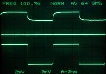
We certainly agree that the early effect of the BC550 is much worse than that of the 2SC2240. My curve tracer shows that at least for the complementary BC560C and 2SA970GR. Square waves, on the other hand, should be seen as an error, as the early effect is perfectly time-invariant. The transistor switches to the other operating point at electronic speed. There is a distortion due to thermal reasons. In the attached green scope photo, I measured a Philips BD137 cascoded with Philips BD137. That's a 380mA CCS. The upper trace is error on the emitter. (2mV/div) We could also say that this is a change in the current of CCS, as it is proportional to it. (90uA/div) Middle trace is the base. Connected to CCS loaded zener. (2mV/div) Lower trace is the collector of the cascoding BD137 transistor. (Sorry forget to note the exact sensitivity. Was around 1...2 Volts/div)
The error is almost purely thermal for the green scope photo. It is cascoded, so the early effect is almost completely ruled out.
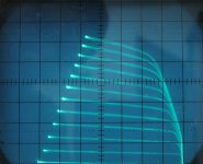
On the BC560C blue traces thermal loops clearly visible. 2SC970GR is better.
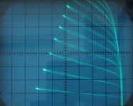
The early effect is responsible for about 20-30% of the error on the color screenshot. The rest is thermal failure. This transistor was not cascoded, so there is a small part that switches at electronic speed due to the early effect.
There's no capacitor connected to these BJTs in any of these tests!
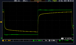
And finally a post that shows my three scopes at once. 🙂
Attachments
Last edited:
What is missing is a correlation between the device thermal behaviour and distortion measurements in an amplifier.
P. Johannet & P. Guuinic - La musicalité des amplificateurs: essai d'une mesure objective.
See fig. 22. That's the measurement of the SE tube amplifier. Compared with other amplifiers. Certainly tube's thermal cut-off frequencies fall into the infrasound region for sure. That's why I say Audio Precision is a junk. They measured more important things in that article 30 years ago.
G. Perrot - Measurement of a Neglected Circuit Characteristic Thanks Peufeu for that doc!
See the fourth tif file. '4.3 correlation with listening tests'
Memory Distortion - Part 6 : The Listening Test
Our forum member Peufeu simulated (not measured) the residual memory of circuits and done a listening test.
Honestly, one of my most shocking experience was when realized how massive and full-bodied bass of a small 3Watt EL84-equipped SE amp had. It had a transformer coupled output.
Based on this experience, the frequency response is certainly not play so large role as it's considered to. I think more or less the frequency response is like white-balance for your eyes. Probably ear can adapt to 1...3 dB errors easily.
Many speaks about ruler flat amplifier response from DC to 100kHz as HQ audio requrirement. But speakers easily has +/-3dB error throughout the audible range!
As I wrote those could be a real audio output of non filtered R-2R DAC. What was that I missed?
You obviously missed a lot of things. First of all you missed the nonsense you wrote.
The reconstruction filter is not a smoothing capacitor. And the vast majority of R2R dacs use oversampling.R-2R DACs produce such waveforms if their output is not smoothed out by a capacitor that degrades sound quality.
Using NOS dacs without any output filter relies on amplifier or speaker (or finally the ear) to do the filtering. Such a signal is as real audio output as DC or RF output from a faulty equipment. Sadly out of ignorance petr_2009 is using this type of signal as a standard audio signal to prove his "hypothesis".
Honestly, one of my most shocking experience was when realized how massive and full-bodied bass of a small 3Watt EL84-equipped SE amp had. It had a transformer coupled output.
A well-known effect. Say you have a 30Hz signal. The amplifier cannot reproduce it with the small xformer, but it distorts heavily producing 60Hz and 90Hz harmonics.
Our sound perception system hears 60Hz and 90Hz and synthesizes the 30Hz fundamental.
The effect has been exploited many decades by Bose, making very small boxes with apparently incredible low reproduction.
If you understand how we hear, you can exploit it!
Jan
well, at first glance the paper you referred to by Guuinic shows a few graphs with signal responses simply due to RC time constants. I haven't read it in any detail as my French is a little slow.
And, the problem with Petr-2009's digitised waveform is that it is the digitised signal, not the reproduced one. Even at 44.1kHz sampling, which I did not originally spot, would not emerge as that waveform after passing through a "reconstruction filter" which is basically a steep slope filter. And that can be implemented digitally.
Regarding your I-V curve plots, how do you determine the difference between a capacitively (Cjc) induced loop and a thermal effect?
Last edited:
Some more thoughts-
I would agree that a thermal time constant could contribute to a signal variation as much as an RC.
I suspect that thermal effects may well have accounted for some of the "transistor sound" in the old days.
Particularly amplifiers with large current and/or voltage variations in the transistors in key positions. Consider the old style PNP input, NPN driver and complementary or quasi-complementary output stage. If the input transistor current is too low, then the thermal variations with signal could be significant. In many old designs (and I have to say, the JLH10) the input stage current is too low I suggest.
If- and this is the point about high gain/high feedback - the signal deviation is small, then the thermal effects reduce.
So when we talk about amplifiers with what I would rather term "thermal hysteresis" we need to be specific about which amplifier. What circuitry and the thermal effects in each transistor.
Have you tried putting the BC550C on a small heatsink and retested the thermal time constant?
THere are however several thermal time constants in a device. There is the junction itself, the collector depletion region where the heat is generated (which includes part of the base). From there there are emitter metallisation and wire bonds (not much heat conducted that way, as I pointed out before) then the collector to mounting tab, the thermal mass of the silicon and metal adding at least two thermal time constants. Then the thermal resistance through the packaging and thermal mass of the package. You can see some of these effects particularly in a power device datasheet where the transient thermal impedance is plotted, which often has several break points. A sort of "inverse" Bode plot if you like, as this is in the time domain.
For small signal transistors the thermal effects are a lot quicker.
What I do find odd is that the audible difference between a 2SC2240 as you mentioned compared with a BC550 if the (main) thermal time constants are both in the middle of the audio band (1kHz vs 3kHz according to your results). That would suggest both devices would have audible effects. That is another reason we need to know the circuit details of any claims between devices.
Last edited:
"In these times, electrolytic capacitors were much larger in size. These larger capacitors did not cause as much error in the signal as the current smaller components. The transistors weren't had so unnecessarily high gain, and maybe that's why they sounded better with their worse C-E to B-E thermal coupling."
Somewhat dubious statements.
Understatement of the year.
G. Perrot - Measurement of a Neglected Circuit Characteristic Thanks Peufeu for that doc!
See the fourth tif file. '4.3 correlation with listening tests'
I suspect much of this was known long before the above paper was presented, particularly in the integration of circuits. it is expected that what is of essential importance is thermal tracking of the input differential pair (if the exists). Effectively as one of the devices heats up the other cools down, hence ought to thermally joined. Current documents (2019) exist as the following:
Thermal Management Challenges and Mitigation
Techniques for Transistor-level 3-D Integration
Thermal management challenges and mitigation techniques for transistor-level 3-D integration - ScienceDirect
Last edited:
"That's why I say Audio Precision is a junk."
Everyone's entitled to an opinion I suppose.
At least it's expensive junk, that ought to respect the tool...
"That's why I say Audio Precision is a junk."
Well, consider this experiment: you test an amplifier where the supposedly linear stages are operating at marginal conditions where power dissipation can significantly alter Vbe's and gains due to a signal excursion.
If these thermal variations have short time constants relative to the signal frequency so that the transistor in question heats and cools with the signal, why would you think any distortion this caused would not be shown up by a standard measurement of THD?
Last edited:
LF test tones are often used with FFTs to look for evidence of thermal distortion. Nothing quite as satisfying to me though as seeing a notched out time domain residual. I suppose if a wav file were saved of the audio signal used for FFT analysis then one could go to the trouble of notching and amplifying a time domain residual from that raw data. Might take some signal averaging to help minimize noise, not sure.
I've done some loop-back measurements with an APx515, mainly frequency response, over the first few hours after switch-on.
I measured something iirc 50mdB over the first half hour, down to 10mdB per next hour. This was also on the same order as the non-flatness I measured. I gave up after 5 hours ;-)
Jan
I measured something iirc 50mdB over the first half hour, down to 10mdB per next hour. This was also on the same order as the non-flatness I measured. I gave up after 5 hours ;-)
Jan
it is expected that what is of essential importance is thermal tracking of the input differential pair (if the exists). Effectively as one of the devices heats up the other cools down, hence ought to thermally joined.
That ought not be the case, an input differential pair should be heating up and cooling down together as their base-collector voltages swing in lock-step and the collector currents will be closely balanced at lower frequencies where feedback is most effective. The common-mode voltage signal should dominate the thermal dissipation at lower frequencies, otherwise you have a problem with the pair being too heavily loaded to be linear in the first place surely?
Consider a pair with 10µA of differential current(*) running at 40V - thats 0.4mW differential heating, or for a half cycle at 20Hz that's ~10µJ thermal energy swing, enough to oscillate 1mm^3 of silicon a few millikelvin I think, so something like a few microvolts of Vbe change.
At these tiny values the thermal changes are as linear as you like simply from the small signal maths. Far too small to generate measurable harmonics. Far smaller than the Vbe changes due to the 10µA of differential current swing in fact, which are the existing source of non-linearity in the pair.
At higher frequencies the differential currents become larger, but the thermal inertia is more effective, so even less worrying.
At very low frequencies where the feedback is no longer operative thermal bonding of input devices can significantly reduce DC offset drift/variation (typically due to uneven convection patterns inside the amp case). This is a more valid reason to thermally bond them.
(*) 10µA into the VAS, 1mA out of the VAS, 100mA out of the driver, 5A out of the output devices.... Not unreasonable values.
For IC designers this is all very important, so there is a whole body of expertise how to lay out chips to minimize thermal drift.
I don't know how they do it today, but early opamps had the output devices physical layout symmetrically and opposite each other on the die to cancel thermal coupling.
Jan
I don't know how they do it today, but early opamps had the output devices physical layout symmetrically and opposite each other on the die to cancel thermal coupling.
Jan
That ought not be the case, an input differential pair should be heating up and cooling down together as their base-collector voltages swing in lock-step and the collector currents will be closely balanced at lower frequencies where feedback is most effective. The common-mode voltage signal should dominate the thermal dissipation at lower frequencies, otherwise you have a problem with the pair being too heavily loaded to be linear in the first place surely?
Hi Mark,
I am not disagreeing with you. What was meant by "essential" was under circumstances that modern technologies have been advanced to the point of something like an OPA1611 op-amp. Figure 14 seems supporting your arguments both in terms of variances in PSRR and CMRR. The CMRR is remarkable at 120dB to 80KHz, or 1 part in 1million. It is expected that, amongst several other parameters, thermal mitigation is also essential.
Who cares the vast majority? Nice try! I said NOS at it's original sample rate.You obviously missed a lot of things. First of all you missed the nonsense you wrote.
The reconstruction filter is not a smoothing capacitor. And the vast majority of R2R dacs use oversampling.
 In that case the reconstruction filter could be only complex analog circuit. Sample rate is fixed at 44.1kHz!
 Any problem with that?Using NOS dacs without any output filter relies on amplifier or speaker (or finally the ear) to do the filtering.
So you admit that NOS can be used without any output filtering!Such a signal is as real audio output as DC or RF output from a faulty equipment. Sadly out of ignorance petr_2009 is using this type of signal as a standard audio signal to prove his "hypothesis".
The vast majority must have a really bad amplifier if it cannot handle such a low power in the ultrasound range. The amplifier hardly emits current in the ultrasonic range. This concern is unnecessary.
Who cares the vast majority? Nice try! I said NOS at it's original sample rate.
Any problem with that?
So you admit that NOS can be used without any output filtering!
The vast majority must have a really bad amplifier if it cannot handle such a low power in the ultrasound range. The amplifier hardly emits current in the ultrasonic range. This concern is unnecessary.
It may be a language issue but you are still missing the point. The discussion was not about whether or not amplifiers can handle such signals but that such signal is not a standard audio signal. You can use NOS without any output filtering if it suits you. I could not care less.
- Home
- Amplifiers
- Solid State
- First cycle distortion - Graham, what is that?