How could you know? How could you say that we defeated all the distortions..?No, it's not, that's the point that is being made but ignored.
I admit that I can't show you an image from an oscilloscope and circle it in paint as it's subtle.
As viruses (which are non-existing to our naked eye) also can cause serious trouble
(in term of relative sensitivity as they can't harm a metal surface just humans).
The same is true if our ears have some "preferences" and special distortion sensitivities.
I also admit that for me me it's just an assumption that as the sound is still not perfect
there still should be some "error" which is probably very tiny and subtle but exists.
So we just have to build a "microscope" to see it with our naked eye as well.
And it also can hide not just in amplitude but in time as well as you can spot it out
only when a few parameters are working together.
It happens all the time but the significance changes of course dramatically with the signal.OK - so it happens on a CD - how often?
0, 10 or several 1000/s
You must have some idea?
My tip is that it mostly happens when the "amplifier state changing" speed is high.
But let's leave it open, let's check what a test shows.
How could I say..? Even a clipping can cause oscillations, it's hard to predict...
And I didn't say that I know everything and I'm already finished with this topic.
I'm just an interested member and try to create a possible scenario for this case as it seems reasonable (for me).
In my mind it's similar when processing a complex video stream and if the
signal is too complex for a decoder stage the system will drop some frames.
How often does it happen? Random, depends on the material, a decoder plugin can count it. 🙂
(And please do not start to say an audio amplifier doesn't drop frames as it's just a metaphore.)
And sorry about using "we", I correct it to "the believers" then. 😉
Last edited:
Your lack of understanding of signal processing make you come to wrong conclusions - also for video - frames are dropped due to processing capacity limitations or loss of information - it's never due to that superman takes a to fast turn. I hope that if you study the field, you can one day come to the same conclusion.
I wish you all the best!
//
I wish you all the best!
//
Anyone claiming that on a CD we have 'instant signal jumps' should educate himself through the Redbook standard.
It always comes as a surprise to discover that the signal coming off a CD is analog, pure and simple.
Jan
It always comes as a surprise to discover that the signal coming off a CD is analog, pure and simple.
Jan
Last edited:
I didn't say that. To be clear I'm saying normal music is bandwidth limited, you need to understand this or you will not be able to further understand the requirements of audio reproduction.How could you know? How could you say that we defeated all the distortions..?
I've given you an example where the ~20kHz BW limit may have an effect on perception, if you are interested in finding out something "new" I suggest you research that.
Perhaps drop the analogies as well, they seem to just add to your confusion, just a radical idea of my own 😉
Last edited:
I was talking about petr_2009.If you're talking about me, you're wrong. My professional activity is not related to audio, for me it is just a hobby.
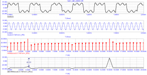
the same amplifier, differs only in correction. One has a signal transit time of 400 ns, while the other has only 40 ns. Loop gain at 20 kHz is the same for both options.
Attachments
-
 Self-1_Bode.png20.5 KB · Views: 201
 -
 Self-2_SCH.png25 KB · Views: 114
 -
 Self-2_Loop-Gain.png47.6 KB · Views: 99
 -
 Self-2_Bode.png18.6 KB · Views: 170
 -
 Self-1_SCH.png24.5 KB · Views: 198
 -
 Self-1_Loop-Gain.png25.7 KB · Views: 196
 -
 Self-1_DIM-30.png40.3 KB · Views: 203
 -
 Self-2_DIM-30.png39.5 KB · Views: 115
the same amplifier, differs only in correction. One has a signal transit time of 400 ns, while the other has only 40 ns. Loop gain at 20 kHz is the same for both options.
You seemed to have a story to tell but why tell it with the two carelessly put-together amps that both have unity gain crossover at about 4.5MHz? Seriously? I bet they have really ugly looking loop gain plot and crappy gain margins as well, one at 0.5dB the other at 2? (Is that why you hid the loop gain plots to begin with?😀😀). I believe many would not hesitate to help you if you could just post the LtSpice schematics or that of whatever simulation tool you use.
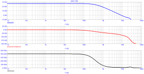
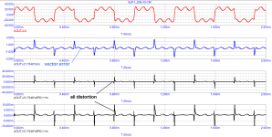
Distortion spectra are usually measured in a band up to 80 kHz. Let's compare a couple of tests. From tests on IMD it can be seen that the noise damping in the sound band and the levels of higher harmonics of the test signals are several times lower in an amplifier with a shorter signal propagation delay time (AMP Self-2).
From the DIM-30 tests, it can be seen that the level of distortion of a 15 kHz signal is at least 2 times higher in an amplifier with a long signal propagation delay time (AMP Self-1). To measure the parameters of a signal with a frequency of 15 kHz, the meander with a frequency of 3.15 kHz was excluded from the output signal.
From the DIM-30 tests, it can be seen that the level of distortion of a 15 kHz signal is at least 2 times higher in an amplifier with a long signal propagation delay time (AMP Self-1). To measure the parameters of a signal with a frequency of 15 kHz, the meander with a frequency of 3.15 kHz was excluded from the output signal.
Attachments
Instead of changing the internals of the amp/schema, why don't you just adjust a filter on the input side to control the amplifiers BW? Then you are in control of what really is the cause - as now, it could be something else generating the distorsion then just the pure BW limit difference - which is how I understand it you blame for the "problem"?
Low BW causes "problem" - is that the thesis?
Or does the "slowness" need to arise at a certain place in an amp in order to be dangerous?
//
Low BW causes "problem" - is that the thesis?
Or does the "slowness" need to arise at a certain place in an amp in order to be dangerous?
//
Both amplifier options have the same DC modes, the quiescent current of the output transistors is 116 mA.
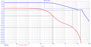
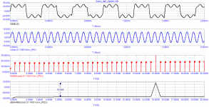
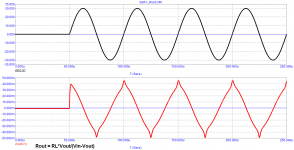
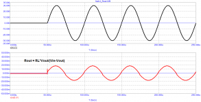
Let's check the output impedance of both amplifier options by applying voltage to the amplifier output through its load as Graham recommended and see their behavior.
And although the NFB depth at a frequency of 20 kHz, both options have the same output impedance of an amplifier with a lower Group Delay and with a frequency of the first pole above 20 kHz, about 2 times lower.
Moreover, it is more linear and in phase with external influences.
Exactly the same behavior of the output impedance and amplifiers without general feedback.
In the first case, the phase of the loop amplification in the entire audio range is equal to 90 degrees (such a mode was praised by someone above), in the second, the phase is almost zero and only to a frequency of 20 kHz is rotated by 10 degrees
Attachments
Last edited:
The input filter you are talking about I usually turn off so as not to be misleading ...Instead of changing the internals of the amp/schema, why don't you just adjust a filter on the input side to control the amplifiers BW? Then you are in control of what really is the cause - as now, it could be something else generating the distorsion then just the pure BW limit difference - which is how I understand it you blame for the "problem"?
//
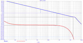
Let's check the output impedance of both amplifier options by applying voltage to the amplifier output through its load as Graham recommended and see their behavior.
Is this how you calculate output resistance Rout = RL * Vout / (Vin - Vout) ? What does those charts show? Time dependent output resistance oscillating between 20mohms and -20mohms? No kidding?
Attachments

In the first case, the phase of the loop amplification in the entire audio range is equal to 90 degrees (such a mode was praised by someone above), in the second, the phase is almost zero and only to a frequency of 20 kHz is rotated by 10 degrees
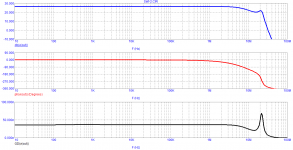
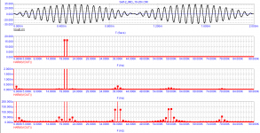
First waveform is distorted due to severe slew limiting (not loop phase shift), consequence of 10x larger compensation capacitor and insufficient current drive capability of the previous stage. Avoidable without FR & phase loop change.
No need for first cycle analysis, problem is perfectly visible in the steady state.
the same amplifier, differs only in correction. One has a signal transit time of 400 ns, while the other has only 40 ns. Loop gain at 20 kHz is the same for both options.
Note that on the graphs with the DIM test at the lowest, their sine amplitudes are almost the same, despite differences in corrections, rise rates, and frequencies of the first pole. The only difference is the response to spikes with sharp fronts, which is not news. And it is quite logical that a less broadband amplifier will give a larger spike and a larger dynamic error when its input is affected by a broadband signal. After all, even filtering the meander in the first order of the filter does not remove absolutely all harmonics, and they have to be worked out by the amplifier.
And what do you see good in the output resistance charts of both options and why is phase matching so important to you?Let's check the output impedance of both amplifier options by applying voltage to the amplifier output through its load as Graham recommended and see their behavior.
And although the NFB depth at a frequency of 20 kHz, both options have the same output impedance of an amplifier with a lower Group Delay and with a frequency of the first pole above 20 kHz, about 2 times lower.
Moreover, it is more linear and in phase with external influences.
Exactly the same behavior of the output impedance and amplifiers without general feedback.
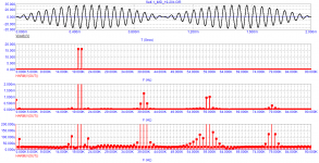
I personally see that on the second chart that you are voting for, at the peak of the test signal being sent, we have the largest static error. At the same time, this error at the peak of the signal tends to zero for the first one. However, the insufficient slew rate does not allow it to work out a similar signal amplitude that is forcibly fed to it at the input. And the effect of doubling the conductivity is added in the form of curvature of the vertices of the triangle.
A test with a smaller amplitude of the input test signal would be more indicative. And at the same time, it would probably be worth determining the voltage rise rates of both models for greater transparency.
To sum up, I do not see any novelty and need to search for new methods of evaluation, if they show the same thing to an understanding person, but under a different sauce. In the same way, the estimation of the GD instead of the direct estimation of broadband by amplitude and phase characteristics is an attempt to replace the primary parameters with secondary ones.
Since "petr_2009" doesn't seem to be interested in sharing a schematic that is readily operable in a simulation tool, I went ahead and re-constructed, with LtSpice, the circuit diagrams of the two amps that he posted Here
Loop gain plot shows us the first amp, inferior according to "petr_2009", has a unity gain crossover at 395KHz, and a gain margin of 25dB. Rock solid stability. Transient analysis with 20KHz 1Vpk sine at the input produces a clean output with estimated distortion of 0.01%.


Loop gain plot for the other amp, much more broadband therefore favored by "petr_2009", however, is in fact an oscillator. It's radically under-compensated by having a unity gain crossover at 4.8MHz, and when the phase turns 180-degree around the loop, the loop gain is at +2dB, shot up by the peaking caused by the 2nd pole. Transient analysis with a 50mVpk 20KHz sine at the input gives us a beautiful output waveform that reminds me of an ac biased tape recorder head.


It's quite clear to me which one to pick between the two.
Loop gain plot shows us the first amp, inferior according to "petr_2009", has a unity gain crossover at 395KHz, and a gain margin of 25dB. Rock solid stability. Transient analysis with 20KHz 1Vpk sine at the input produces a clean output with estimated distortion of 0.01%.
Loop gain plot for the other amp, much more broadband therefore favored by "petr_2009", however, is in fact an oscillator. It's radically under-compensated by having a unity gain crossover at 4.8MHz, and when the phase turns 180-degree around the loop, the loop gain is at +2dB, shot up by the peaking caused by the 2nd pole. Transient analysis with a 50mVpk 20KHz sine at the input gives us a beautiful output waveform that reminds me of an ac biased tape recorder head.
It's quite clear to me which one to pick between the two.
Nattawa, try to calm him down by tightening the correction. Apparently, the difference in the models used is affected. I didn't find any visual differences between the diagrams. But you still need a working version for comparison, albeit a little more "squeezed".
Loop gain plot for the other amp, much more broadband therefore favored by "petr_2009", however, is in fact an oscillator. It's radically under-compensated by having a unity gain crossover at 4.8MHz, and when the phase turns 180-degree around the loop, the loop gain is at +2dB, shot up by the peaking caused by the 2nd pole. Transient analysis with a 50mVpk 20KHz sine at the input gives us a beautiful output waveform that reminds me of an ac biased tape recorder head.
It's quite clear to me which one to pick between the two.
It is easy to get higher slew rate but still stable. You can add "input inclusive compensation" aka Douglas Self, so you can reduce Miller compensation. Or you can use Transitional Miller Compensation (TMC).
- Home
- Amplifiers
- Solid State
- First cycle distortion - Graham, what is that?