It is easy to get higher slew rate but still stable. You can add "input inclusive compensation" aka Douglas Self, so you can reduce Miller compensation. Or you can use Transitional Miller Compensation (TMC).
"....get higher slew rate but still stable." Exactly. It's a game of tradeoff after all. You can't gain some without losing something else. What matters in playing that game is to know where to stop to strike a balance. In the particular case one of the amps was pushed beyond its stability limit in chasing the illusive so-called "first cycle" fidelity, yet was nonetheless favored by our "lecturer". That's what I tried to point out.
And, no, I would not touch the miller capacitor in amp #1 unless there is a good reason. Its 400KHz unity gain crossover is quite decent and it has robust stability. It's slew rate is much more than adequate for audio, and its estimated 0.01% THD-20 makes it an excellent performer. You want a unity gain crossover at 800KHz instead? go for it, not a big deal, you're not sacrificing a lot of gain margin by doing that. But not 4.8MHz please.
And, no, I would not touch the miller capacitor in amp #1 unless there is a good reason. Its 400KHz unity gain crossover is quite decent and it has robust stability. It's slew rate is much more than adequate for audio, and its estimated 0.01% THD-20 makes it an excellent performer. You want a unity gain crossover at 800KHz instead? go for it, not a big deal, you're not sacrificing a lot of gain margin by doing that. But not 4.8MHz please.
Jan Didden built 10Mhz full power bandwidth amplifier.
I sim small amplifier with ULGF around 4MHz - 5 MHz. My friend built it, and it is stable.
nattawa, If you are convinced that Miller's correction is the best type of correction, then I'm not going to overpersuade you. Continue to be delusional and further - use Cdom to the maximum. As far as your simulation results are concerned, it is your problem that you cannot tune the model. If the model is not stable, then it does not work! I gave a graph of the loop gain from which the stability margins are visible.It's quite clear to me which one to pick between the two.
I am convinced that a wider and faster amplifier will more accurately amplify complex signals other than sinusoidal ones. This is fully consistent with theory.
Let me remind you that above I gave the operation of the same voltage amplifier with four types of correction, and only one of them from John Linsley Hood in 1972 deserves attention.
Attachments

Jan Didden built 10Mhz full power bandwidth amplifier.
I sim small amplifier with ULGF around 4MHz - 5 MHz. My friend built it, and it is stable.
……Yes, but not with straight Miller compensation, which is what petr_2009's amp being on topic is.
nattawa, If you are convinced that Miller's correction is the best type of correction, then I'm not going to overpersuade you. Continue to be delusional and further - use Cdom to the maximum.
I never said anything was the best, what part in my post did you pick that up from? What I was certain about was the choice between a stable amp and an oscillator, both are offered by you, by the way. Did I not put it clearly enough?
As far as your simulation results are concerned, it is your problem that you cannot tune the model. If the model is not stable, then it does not work! I gave a graph of the loop gain from which the stability margins are visible.
The problem is with you, petr-2009, who sees a teacher in yourself, refusing to present the schematics and models in a form that they could be simulated on your students computers. Your were asked of it, but you never responded. Why do you refuse to post your schematics and models for the world to witness and prove stability? Don't you think having your circuit and models simulated on my computer, and rendering the same result, the best way of convincing me, or anyone else in doubt?
I should never have had to reconstruct your circuit and simulated on them to begin with. Once I had to have done it and saw the oscillation, what you displayed in your graphs became too good to be true. I proofread the reconstructed and they are identical to yours. Fellow member "fargo" proofread them too.
What do you mean by "tune the model" when it's unstable? Tweaking the transistor models? To improve gain margin when there is none?
.
I am convinced that a wider and faster amplifier will more accurately amplify complex signals other than sinusoidal ones. This is fully consistent with theory.
Let me remind you that above I gave the operation of the same voltage amplifier with four types of correction, and only one of them from John Linsley Hood in 1972 deserves attention.
Irrelevant.
But not to listen to. It was a piece of test equipment.Jan Didden built 10Mhz full power bandwidth amplifier.
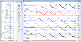
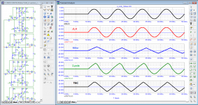
According to the petr_2009 models, I repeated the loop gain test without changing any ratings or settings in the amplifier itself. The contour gain graph corresponds to the one presented earlier by the author. Nominally, when using this particular model, a comparison can be made, since it is stable.

"....get higher slew rate but still stable." Exactly. It's a game of tradeoff after all. You can't gain some without losing something else. What matters in playing that game is to know where to stop to strike a balance. In the particular case one of the amps was pushed beyond its stability limit in chasing the illusive so-called "first cycle" fidelity, yet was nonetheless favored by our "lecturer". That's what I tried to point out.
Sorry, but bandwidth and slew rate have, in a general case (not necessary Miller) nothing to do with each other. They are more or less (depending on the topology) independent variables; an amplifier can have large bandwidth and low slew rate, or the other way around.
That's because they have different scopes; while bandwidth (and the associated rise time) are small signal parameters defined when all devices are in a linear region, slew rate is essentially a large signal parameter; slew rate occurs when an amplifier stage enters a fundamental non linear region, where at least one device is saturated or blocked.
The proof is in the pudding; a current feedback amplifier can be compensated for a, say, 1MHz ULGF, while maintaining an 1000V/uS slew rate. The Stochino amplifier uses a current dumping schema to increase the slew rate to 300MHz well beyond what the standard compensation capacitor would allow.
So other than in the standard LTP and Miller compensated VAS topology there is no necessary trade between bandwidth and slew rate. No pun intended, but the confusion between rise time and slew rate, and the lack of understanding the differences between small and large signal properties, are by far the most common issues in DIY audio.
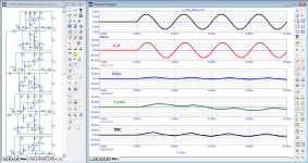
As an addition, I will give graphs of the transition characteristic, which will help us to estimate the slew rate and also the stability of both models.
Calculated SR values: 1 number-178-195 (front-fall) V/us; 2 number-27 V/us


Calculated SR values: 1 number-178-195 (front-fall) V/us; 2 number-27 V/us
Sorry, but bandwidth and slew rate have, in a general case (not necessary Miller) nothing to do with each other. They are more or less (depending on the topology) independent variables; an amplifier can have large bandwidth and low slew rate, or the other way around.
That's because they have different scopes; while bandwidth (and the associated rise time) are small signal parameters defined when all devices are in a linear region, slew rate is essentially a large signal parameter; slew rate occurs when an amplifier stage enters a fundamental non linear region, where at least one device is saturated or blocked.
The proof is in the pudding; a current feedback amplifier can be compensated for a, say, 1MHz ULGF, while maintaining an 1000V/uS slew rate. The Stochino amplifier uses a current dumping schema to increase the slew rate to 300MHz well beyond what the standard compensation capacitor would allow.
So other than in the standard LTP and Miller compensated VAS topology there is no necessary trade between bandwidth and slew rate. No pun intended, but the confusion between rise time and slew rate, and the lack of understanding the differences between small and large signal properties, are by far the most common issues in DIY audio.
Yes!
. The Stochino amplifier uses a current dumping schema to increase the slew rate to 300MHz well beyond what the standard compensation capacitor would allow..
At least until it catches fire. Still kept playing though.
Sorry, but bandwidth and slew rate have, in a general case (not necessary Miller) nothing to do with each other. They are more or less (depending on the topology) independent variables; an amplifier can have large bandwidth and low slew rate, or the other way around.
That's because they have different scopes; while bandwidth (and the associated rise time) are small signal parameters defined when all devices are in a linear region, slew rate is essentially a large signal parameter; slew rate occurs when an amplifier stage enters a fundamental non linear region, where at least one device is saturated or blocked.
The proof is in the pudding; a current feedback amplifier can be compensated for a, say, 1MHz ULGF, while maintaining an 1000V/uS slew rate. The Stochino amplifier uses a current dumping schema to increase the slew rate to 300MHz well beyond what the standard compensation capacitor would allow.
So other than in the standard LTP and Miller compensated VAS topology there is no necessary trade between bandwidth and slew rate. No pun intended, but the confusion between rise time and slew rate, and the lack of understanding the differences between small and large signal properties, are by far the most common issues in DIY audio.
Thank you for the insight. You are right about every count.
In the context of the conversation, about amplifier #1 petr_2009 demonstrated, indeed of a standard LTP and Miller compensated VAS topology, would it be fair to say its slew rate is tied to stability margins?
Syn08 it would be worth clarifying what "bandwidth" we are talking about. If about the one that is associated with the small-signal parameter "Gain bandwidth product", then he is right. However, you can also think about "full power bandwidth", which is directly related to slew rate.
As far as I understood, the colleague meant rather the former.
As far as I understood, the colleague meant rather the former.
to increase the slew rate to 300MHz well beyond what the standard compensation capacitor would allow.
That would be of course be 300V/uS, sorry for the typo.
Syn08 it would be worth clarifying what "bandwidth" we are talking about. If about the one that is associated with the small-signal parameter "Gain bandwidth product", then he is right. However, you can also think about "full power bandwidth", which is directly related to slew rate.
As far as I understood, the colleague meant rather the former.
Full power bandwidth is indeed related to slew rate limitations; as such, this is also a large signal concept, and is defined as the frequency at which the AC peak-to-peak output voltage swing is still equal to the available DC output voltage swing. The relation to slew rate is simple, FPBW=SR/(2*PI*Vs) where Vs is the DC output swing capability of the amplifier. While this expression may look similar to the relationship between bandwidth and rise time, they are fundamentally different (and have different values).
Last edited:
Sorry, but bandwidth and slew rate have, in a general case (not necessary Miller) nothing to do with each other. They are more or less (depending on the topology) independent variables; an amplifier can have large bandwidth and low slew rate, or the other way around.
That's because they have different scopes; while bandwidth (and the associated rise time) are small signal parameters defined when all devices are in a linear region, slew rate is essentially a large signal parameter; slew rate occurs when an amplifier stage enters a fundamental non linear region, where at least one device is saturated or blocked.
The proof is in the pudding; a current feedback amplifier can be compensated for a, say, 1MHz ULGF, while maintaining an 1000V/uS slew rate. The Stochino amplifier uses a current dumping schema to increase the slew rate to 300V/us well beyond what the standard compensation capacitor would allow.
So other than in the standard LTP and Miller compensated VAS topology there is no necessary trade between bandwidth and slew rate. No pun intended, but the confusion between rise time and slew rate, and the lack of understanding the differences between small and large signal properties, are by far the most common issues in DIY audio.
Full power bandwidth is indeed related to slew rate limitations; as such, this is also a large signal concept, and is defined as the frequency at which the AC peak-to-peak output voltage swing is still equal to the available DC output voltage swing. The relation to slew rate is simple, FPBW=SR/(2*PI*Vs) where Vs is the DC output swing capability of the amplifier. While this expression may look similar to the relationship between bandwidth and rise time, they are fundamentally different (and have different values).
Exactly right.
In the context of the conversation, about amplifier #1 petr_2009 demonstrated, indeed of a standard LTP and Miller compensated VAS topology, would it be fair to say its slew rate is tied to stability margins?
Yes, for a LTP and Miller compensated topology slew rate and stability are coupled. The SR is determined by the LTP bias current, which is the maximum current available to charge the Miller compensation capacitor. Everything else being unchanged, the slew rate and ULGF are both inverse proportional to the Miller capacitor value.
Since stable audio amplifiers are minimum phase systems (so, apud Bode, the phase can be uniquely derived from the slope of the magnitude) it is fair to conclude that, in this particular case, the stability margins and the slew rate are tightly coupled.
But not to listen to. It was a piece of test equipment.
No matter he use for test equipment, but it can be done.
- Home
- Amplifiers
- Solid State
- First cycle distortion - Graham, what is that?