Its fun (and inspirational) to view ongoing progress in your system.
What might happen to "tone" if you temporarily added a "bypass" cap across one of the highpass capacitors? Would that degrade the experience ?
A few days ago a fellow Karlsonite was mentioning the difficulty of convincingly reproducing a violin's spatial (and transient) characteristics and said something about using 3 -K-tubes - One in normal fashion, flanked left and right by tubes turned 90 degrees. These extra tubes would be crossed in at a higher point than the main treble tube.
I'll have to bring the discussion up again for clarification as he said something about "not stereo". I don't know if that means with two channels, a recording with the violin fully panned to one channel (?)
Last edited:
Good morning Freddi,
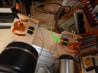
that bypass-capacitor is EXACTLY what i'm doing now. During the build-up of the (external) crossover-boards i added space + wires next to the XO-capacitor itself to play with an added bypass-capacitor.
Yes, it changes the (high) reproduction but not in a qualitative way but in a change in taste. It doesn't get better; it's getting different.
Currently i use a mica-cap as bypass and it seems to bring out more details but on the hard side. Its taste ! Someone will like it; somebody else not.
For my planned tweeter amp i know i will not use that same mica as coupling capacitor because that would simply be too much.
Time for experiments: soo much caps to chooce from and it is an easy change in my set as everything at the crossover-boards is open/exposed.
Regards,
Reinout
Attachments

another way to create a well damped"inert" - K-tube is to use layers of wood veneer soaked in glue then held to a form with rubber bands as with Carl's 1" ID tube in this test coupler. I think Carl has experimented with oval K-tube per Karlson's Open End Waveguide patent using this technique.
Attachments
@ReinoutdV
Do you have any updates on how the system is evolving ?
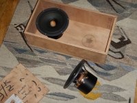
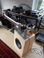
Instead of a large K-tube for midrange I will try a cone speaker (8PL21) in this 8" mid-K built by a very good friend. A $65 1.5" driver will drive a K-tube. I'm hoping for good peak spl rather than "finesse" 😀
Do you have any updates on how the system is evolving ?
Instead of a large K-tube for midrange I will try a cone speaker (8PL21) in this 8" mid-K built by a very good friend. A $65 1.5" driver will drive a K-tube. I'm hoping for good peak spl rather than "finesse" 😀
Attachments

Good evening Freddi,
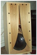
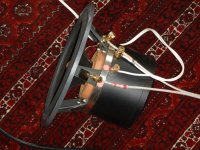
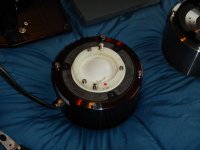
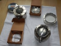
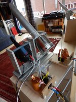
i walked that road also with very nice Fertin 20EX field coils (8" ). See pictures..
But the K-tube / compression driver midrange give better results. It has the same fast transients as the K-tube / compression driver tweeter.
The CNC-work on the K-tubes are extremely slow........Corona-effects kicked in at that production facility so these orders were (logically) pushed aside in order to survive. I simply have to wait.
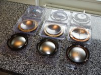
That does not mean there is no progress as i am currently exploring all kinds of diaphragms for the Von Langa field coil tweeter (the compression driver behind the tweeter K-tube).
Currently i have available:
- American aluminium (these are made on/with original Altec tooling; GPA bought everything from Altec)
- Chinese aluminium
- Chinese titanium
- Russian paper
I'm waiting for the Radian mylar/aluminium so i can have a real broad test ahead. The Radians are on backorder so again......waiting.
The physical differences are great as well as the quality / workmanship. Already surprising results with the early tests but i want to burn in those diaphragms properly and i am waiting for the last test subject.
Of course i'm still waiting for the availability of beryllium diaphragms ......
Regards,
Reinout
i walked that road also with very nice Fertin 20EX field coils (8" ). See pictures..
But the K-tube / compression driver midrange give better results. It has the same fast transients as the K-tube / compression driver tweeter.
The CNC-work on the K-tubes are extremely slow........Corona-effects kicked in at that production facility so these orders were (logically) pushed aside in order to survive. I simply have to wait.
That does not mean there is no progress as i am currently exploring all kinds of diaphragms for the Von Langa field coil tweeter (the compression driver behind the tweeter K-tube).
Currently i have available:
- American aluminium (these are made on/with original Altec tooling; GPA bought everything from Altec)
- Chinese aluminium
- Chinese titanium
- Russian paper
I'm waiting for the Radian mylar/aluminium so i can have a real broad test ahead. The Radians are on backorder so again......waiting.
The physical differences are great as well as the quality / workmanship. Already surprising results with the early tests but i want to burn in those diaphragms properly and i am waiting for the last test subject.
Of course i'm still waiting for the availability of beryllium diaphragms ......
Regards,
Reinout
Attachments


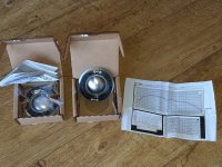
And today the Radians 1228-8 arrived. Very nicely made, serious packing, frequency plot (unique to diaphragm), etc.....good first impression.
But for the groupfoto they were too late as the paper Russian paper diaphragms are already installed and running in.
Nevertheless: the testgroup is complete.
Of course i would like to have a beryllium pair as well but that will be quite difficult at this moment as there is no production. And if the production starts i probably will be shocked by the prices.
Diaphragm-time !
Regards, Reinout
Attachments
Thanks Reinout,
I am very curious about your impressions. You must be a very patient person as to align these tiny devices can sometimes be a pain from my experiences. What is your alignment and verification procedure?
I am very curious about your impressions. You must be a very patient person as to align these tiny devices can sometimes be a pain from my experiences. What is your alignment and verification procedure?
What is the benefit, outside of adjustable field strength, of a field coil magnet over a permanent magnet on a speaker driver?
Hi Freddi,
that paper diaphragm is indeed interesting ! Been playing with it for some time (running in) but serious impressed with its performance already. Please allow me some time for a proper comparison between the current 5 versions.
Good evening Egellings,
For all field coil pros and cons please use the "search" mode on this forum. There are many many many posts on this topic. For me the biggest benefit of field coils is the ability to change some parameters that are fixed by nature at permanent magnet drivers.
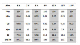
As an example i've added some specs of the Supravox 285EXC. Look at the changing Qts and BL with changing voltages from 6 to 12 volt.
With permanent magnets you must optimise the enclosure to the fixed parameters. With a field coil you can optimise the driver to the enclosure. Of course within limits but you simply hear it when it is optimised.
Regards,
Reinout
that paper diaphragm is indeed interesting ! Been playing with it for some time (running in) but serious impressed with its performance already. Please allow me some time for a proper comparison between the current 5 versions.
Good evening Egellings,
For all field coil pros and cons please use the "search" mode on this forum. There are many many many posts on this topic. For me the biggest benefit of field coils is the ability to change some parameters that are fixed by nature at permanent magnet drivers.
As an example i've added some specs of the Supravox 285EXC. Look at the changing Qts and BL with changing voltages from 6 to 12 volt.
With permanent magnets you must optimise the enclosure to the fixed parameters. With a field coil you can optimise the driver to the enclosure. Of course within limits but you simply hear it when it is optimised.
Regards,
Reinout
Attachments
Hi Reinout
Besides any news regarding your system, would you know of anyone experimenting with bass and/or midbass Karlson type who would be willing to share ideas ?
Best wishes,
Freddy
Besides any news regarding your system, would you know of anyone experimenting with bass and/or midbass Karlson type who would be willing to share ideas ?
Best wishes,
Freddy
perhaps a more pertinent question -
There are a number of tube aspect and slot possibilities (exponential, ellipse, parabolic) I can tell WVL's tube for a dual woofer setup is not pure ellipse nor expo.
Are there certain tube ratios and slots which work better than others regardless of the driver ? (within reason)
How much of that would depend upon the angle of the tube? If it tilts a lot "down" then I would assume a wide horizontal pattern is radiated from the narrow slot. Also, the highest frequencies would tend to go straight down the tube. In practice this seems to sound very good.
Good morning Freddi,
i'm certainly not alone here with K-tube efforts; but the other users are not active on this forum (or any forum for that matter...).
My system is simply dwarved by their audio-efforts.
One of the other users makes only use of a K-tube almost as a super-tweeter (10K +). K-tube almost pointing at you.
One of the other users makes use of separate K-tubes for mid and for high; just like my set-up. K-tubes at high angles
All our slots are exponential; what WVL uses i don't know.
To our surprise lengths and/or sizes didn't really matter as much as anticipated. A straightforward 1" version is just as performing as a 2" version (with longer tube-size). Of much more importance was resonance control of the K-tube.
Also throat adapters to use 1" / 1.4" / 2" drivers on 1" or 2" K-tubes were not really downgrading performance. Which makes switching/swapping of drivers easy to execute.
Our audio-group does not use K-cabinets for bas.
With the angle of the K-tube you can optimise sound coverage in your room. Here acoustics come into play; we don't have golden rules for implementation.
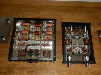
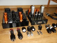
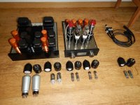
New developments here:
- tweeteramp is ready. Burn-in time ! It's a real 1 Watt performer with options to use really different tubes. For the input tube the Ce / 4P1L or AC100 can be used. For the output tube you can use the ED111 / 6S4 / 12B4 or ML6. All combinations allowed as the convertor sockets contain also the needed compensation resistors etc.
Pictures included.
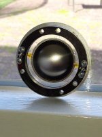
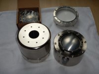
- 2" WVL compression driver available. Currently finding out the nicest combination of this serious field coil driver with different diaphragms. Pictures included.
Regards, Reinout
i'm certainly not alone here with K-tube efforts; but the other users are not active on this forum (or any forum for that matter...).
My system is simply dwarved by their audio-efforts.
One of the other users makes only use of a K-tube almost as a super-tweeter (10K +). K-tube almost pointing at you.
One of the other users makes use of separate K-tubes for mid and for high; just like my set-up. K-tubes at high angles
All our slots are exponential; what WVL uses i don't know.
To our surprise lengths and/or sizes didn't really matter as much as anticipated. A straightforward 1" version is just as performing as a 2" version (with longer tube-size). Of much more importance was resonance control of the K-tube.
Also throat adapters to use 1" / 1.4" / 2" drivers on 1" or 2" K-tubes were not really downgrading performance. Which makes switching/swapping of drivers easy to execute.
Our audio-group does not use K-cabinets for bas.
With the angle of the K-tube you can optimise sound coverage in your room. Here acoustics come into play; we don't have golden rules for implementation.
New developments here:
- tweeteramp is ready. Burn-in time ! It's a real 1 Watt performer with options to use really different tubes. For the input tube the Ce / 4P1L or AC100 can be used. For the output tube you can use the ED111 / 6S4 / 12B4 or ML6. All combinations allowed as the convertor sockets contain also the needed compensation resistors etc.
Pictures included.
- 2" WVL compression driver available. Currently finding out the nicest combination of this serious field coil driver with different diaphragms. Pictures included.
Regards, Reinout
Attachments

Hello Reinout
that's a gorgeous assortment of "stuff" to sort and enjoy !
re: 10K - up K-tube, what length does it have?
Best wishes,
Freddy
that's a gorgeous assortment of "stuff" to sort and enjoy !
re: 10K - up K-tube, what length does it have?
Best wishes,
Freddy
Good morning Freddi,
That would be an original "Transylvania Power Company" K-tube as my CNC-order is still not finished........
The length of that CNC-version will be the same as the original but the walls will be in different thicknesses in order to supress standing waves / resonances.
Regards, Reinout
That would be an original "Transylvania Power Company" K-tube as my CNC-order is still not finished........
The length of that CNC-version will be the same as the original but the walls will be in different thicknesses in order to supress standing waves / resonances.
Regards, Reinout
Transylvania tube
When I experimented with a set of homemade Transylvania tubes, which I thought sounded great, I found a couple things that I would want to experiment further on.
Because the highest frequencies tend to travel straight down the tube, you don't get good dispersion, and get beaming. I hate beaming.... I did try placing an insulated 12 guage wire into the tube (perpendicular to the tube) deep down to act as a diffuser, but it did not work all that well. I could hear the highest frequencies if I aimed the tube straight at me but with beaming (even with the wire as a diffuser) which I did not like - but angling the tube, even with the wire present, did not disperse the highest frequencies and they seemed to mostly be missing. I would like to try different sizes of diffusers, and different placements for the diffusers, and maybe even multiple diffusers.
The other thing to try is to start the tube out larger, narrow it down, and maybe expand the tube out again to see if that disperses the high frequencies. So I would start out with a 3/4 inch tube which matches the exit of the compression driver and transition it down to a 3/8 inch tube to enable dispersing the highest frequencies, but I wonder if the lower frequencies will get pinched too much with the smaller diameter tube.
Right now I have Lowthers in front waveguides, and I am trying to see how good I can get the high frequencies relying on the Lowther whizzer. Once I get the Lowther optimized, I will also try out a Transylvania tube to see which I prefer.
Retsel
First of all, thanks to @freddi for directing me to this thread. Secondly, this is fascinating!
So I have two compression drivers, a Pyle PDS521, and a Miyako DU-100.
Both drivers have a 1 3/8" (1.375" or 34.925mm) diameter screw thread throats, and I'd like to combine them as the Pyle driver can cover 1kHz-20kHz, and the Miyako can cover 150Hz-6kHz.
What size would I need for each K-Tube to use these as a 2-way system? I'd imagine a crossover of 4kHz would be appropriate.
Thanks, and my compliments to the great designs going on in this thread 🙂
Dan
I think it is time for K Tube experiments again. Since I built a multicell horn for my JBL2445 using a 3D printer, I think I should also print some 2" single and double slotted tubes.
ReinoutdV, were there any measurements on the K-Tubes? I would be interested especially in the mid tube. My measurements (and DonVK's simulations) show interesting dispersion properties. I also liked the sound when adjusted properly. The only downside to K-Tubes was that they do not have any gain like horns do (or that is what I think).
ReinoutdV, were there any measurements on the K-Tubes? I would be interested especially in the mid tube. My measurements (and DonVK's simulations) show interesting dispersion properties. I also liked the sound when adjusted properly. The only downside to K-Tubes was that they do not have any gain like horns do (or that is what I think).
Good evening Pelanj,
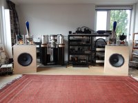
the sound of a K-tube is OK; nothing wrong with that....on the contrary (see picture of current set; ALL drivers are field coils by now....).
Indeed there is no gain like horns. And another item is indeed dispersion; but that is very very subjective/personal. Noted that some readers/writers were not too happy with the small focussing / radiating area. For me it is exactly the contrary as the seriously broad dispersion makes too many room reflections which lead to less focus.
Important is the length of the tube. The "original" K-tube ("transylvania power company") is rather short and this leads to a broad dispersion. So my next K-tube will be longer so a can focus more.
Of note: the dispersion has about a 20 degrees vertical coverage so it is essential that you can "aim" the K-tube at your listening spot.
Not really a surprise as when these original K-tubes were introduced the were meant for small halls/venues covering the horizontal plane to the max. And with the preset fix on the enclosures the correct dispersion angle was aimed at the audience. Hence the name "sound laser".
Very happy with my contraptions so i can aim the K-tubes. The 2" has the correct length: good dispersion around the listening position.
The 1" K-tube is simply too short; will be redone (including different/varying wall-thicknesses).
Maybe i'll let that 2" long K-tube manufacture ?! Thanks for the drawings.
Regards,
Reinout
Attachments
- Home
- Loudspeakers
- Multi-Way
- Fieldcoil + K-tube