More Help/Suggestions
Thanks for the resister tip. Just to clarify you are referring to the last resister before you connect to the Vifa, correct? I think the value in the plan calls for an 8ohm. I should not mess with the 15ohm value earlier on?
Would changing to Mills resisters from the Parts Express one's I originally bought net any improvement?
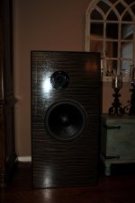
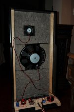
I have attached a few photos and I am still questioning my decision to put the cross brace at the top of the baffle. Should I cut that out? An easy fix with a jig saw if that will help to improve things.
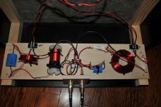
I have never been to hung up on fancy wire and on these I just used stranded 16 gauge electrical hook up wire. Does any one have other suggestions on different wire?
I am currently driving these with an Onkyo TX-NR818 A/V receiver. I know there are better amps out there, but this is not too shabby. I have a Parasound New Classic model 275 I could use instead if that would make a difference.
Thanks all for your input.
Thanks for the resister tip. Just to clarify you are referring to the last resister before you connect to the Vifa, correct? I think the value in the plan calls for an 8ohm. I should not mess with the 15ohm value earlier on?
Would changing to Mills resisters from the Parts Express one's I originally bought net any improvement?
I have attached a few photos and I am still questioning my decision to put the cross brace at the top of the baffle. Should I cut that out? An easy fix with a jig saw if that will help to improve things.
I have never been to hung up on fancy wire and on these I just used stranded 16 gauge electrical hook up wire. Does any one have other suggestions on different wire?
I am currently driving these with an Onkyo TX-NR818 A/V receiver. I know there are better amps out there, but this is not too shabby. I have a Parasound New Classic model 275 I could use instead if that would make a difference.
Thanks all for your input.
Correct, the last resistor that connects to the vifa. I've been listening to mine with the 6.5ohm this morning and it actually sounds pretty good with my vinyl setup. When I move to digital sources it gets pretty harsh. I'm thinking that the 7ohm will be the best for my setup. If you haven't added the optional woofer trap then I highly recommend it. I didn't do it at first and it made a substantial difference. I would call it mandatory not optional.
As far as the difference between mills and PE, from what I've read you should not hear an audible difference but the mills have more substancial leads and hold up better to swapping. The PE leads are very flexible and I've broken one already while swapping.
As far as the difference between mills and PE, from what I've read you should not hear an audible difference but the mills have more substancial leads and hold up better to swapping. The PE leads are very flexible and I've broken one already while swapping.
Thanks for the resister tip. Just to clarify you are referring to the last resister before you connect to the Vifa, correct? I think the value in the plan calls for an 8ohm. I should not mess with the 15ohm value earlier on?
Would changing to Mills resisters from the Parts Express one's I originally bought net any improvement?
I have attached a few photos and I am still questioning my decision to put the cross brace at the top of the baffle. Should I cut that out? An easy fix with a jig saw if that will help to improve things.
I have never been to hung up on fancy wire and on these I just used stranded 16 gauge electrical hook up wire. Does any one have other suggestions on different wire?
I am currently driving these with an Onkyo TX-NR818 A/V receiver. I know there are better amps out there, but this is not too shabby. I have a Parasound New Classic model 275 I could use instead if that would make a difference.
Thanks all for your input.
Could the CD output have a "too high Q" in the final filter, giving an exaggerated HF output that is being reproduced as "harshness" by the treble driver?
And if the treble driver has a resonance that coincides with the CD peak, then that would make it sound even worse.
And if the treble driver has a resonance that coincides with the CD peak, then that would make it sound even worse.
And a few more.
A couple more.
A couple more.
Attachments

Last edited:
Thanks Andrew and taberahkj for the feedback. I'll play with the resister values a bit. I think a big part of my initial impression was tarnished by a bad recording on the CD. Any thoughts on my wiring? should I try anything different?
Wasn't a CD player. I was playing through the crappy DAC in my phone. I don't play CD's much anymore. Mostly Vinyl and occasionally mp3 these days. As far as the wiring I'll let someone with more experience look that over. I'm new to this stuff. All I can say is that I haven't posted pictures of my wiring for a reason 🙂 Your's looks good next to my soldering skills.
Could the CD output have a "too high Q" in the final filter, giving an exaggerated HF output that is being reproduced as "harshness" by the treble driver?
And if the treble driver has a resonance that coincides with the CD peak, then that would make it sound even worse.
Last edited:
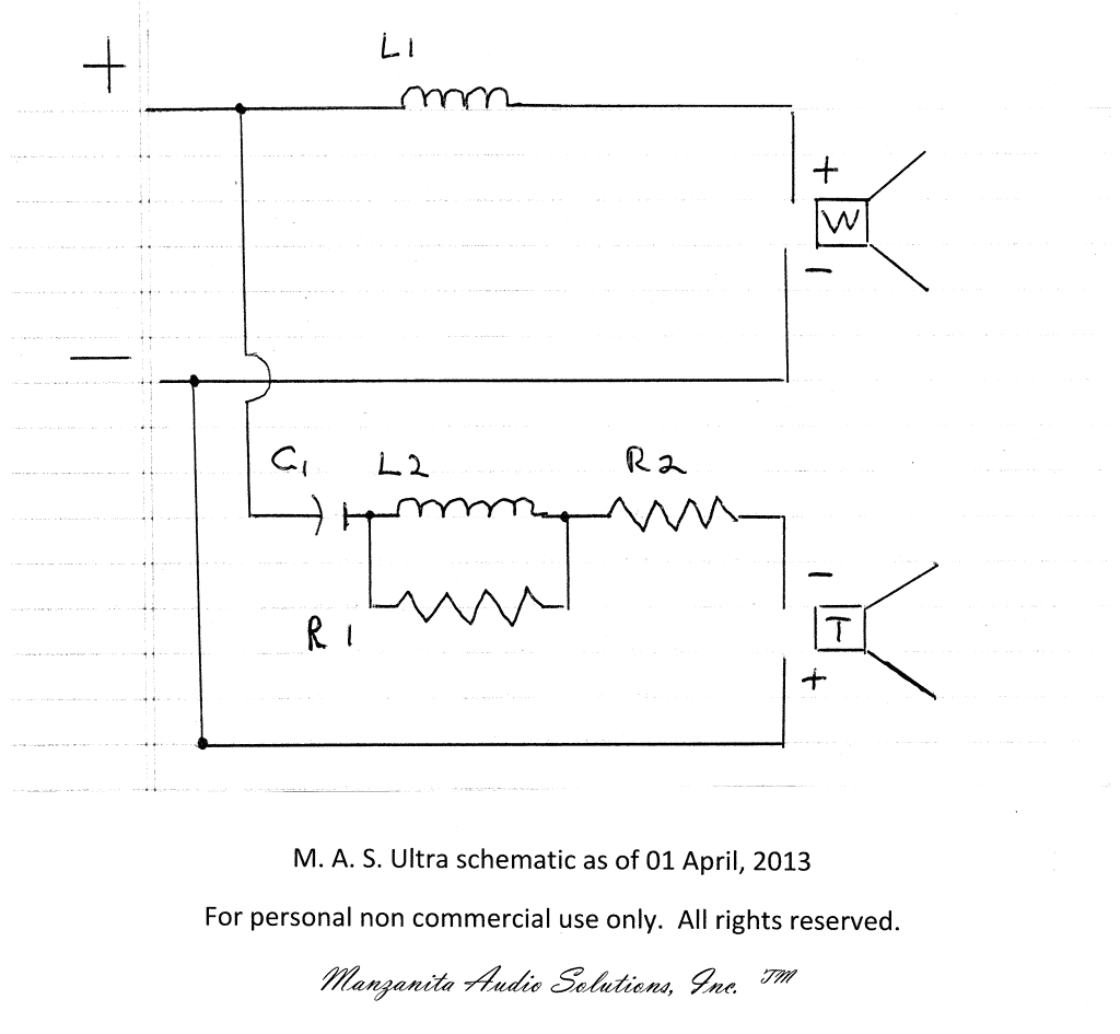
Let's have a look at the crossover and talk about what each parts does. That can help you in understanding what happens when you make changes. And you should make some change to tune this to your room.
When adjusting the crossover, you generally leave L1 alone. It's the base of your bass. 😉
Adjusting the value of R2 will bring the overall level of the tweeter up and down (and slightly change the high pass frequency).
Adjusting the value of R1 will affect the tonality of the tweeter. It adjusts how much top end the tweeter has or does not have. Think of it as a hinge that tilts the response up or down. Lower resistance tilts UP, higher resistance tilts DOWN.
Once you are aware of what you are adjusting, it's time to listen for the changes. Hearing the difference between the level of the tweeter and its tonality can be difficult, but you'll learn by doing and listening.
If you really want to fine tune, you can put variable resistances in place of R1 and R2 and fine tune to your heart's content.
You might try something around a 30 ohm pot for R1 and 12 ohms for R2.
Using one leg of an L-Pad can work if you don't find the power potentiometers.
I hope that clears things up a little and can help guide you in your adjustments and tweaking.
- L1: is the big inductor on the woofer. It rolls off the top end of the woofer (a lot) making it more or less flat up to the point where the tweeter takes over.
- C1: is the high pass filter for the tweeter. This cap blocks the bass from getting to the tweeter.
- R2: This resistor lowers the overall level of the tweeter to match it to the woofer's level. It also changes the impedance of the tweeter circuit, which will affect how C1 works.
- R1+L2: This is the tweeter trap. The inductor is a low pass filter, just like L1 on the woofer. It is a much smaller value, so it works at a higher frequency.
- R1: This resistor partially bypasses the filter effect of L2. If it weren't there, the top end of the tweeter would be far too attenuated. R1 lets some highs and lows go around the L2 coil. By changing the value of R1, you change how much effect L2 has on the tweeter.
When adjusting the crossover, you generally leave L1 alone. It's the base of your bass. 😉
Adjusting the value of R2 will bring the overall level of the tweeter up and down (and slightly change the high pass frequency).
Adjusting the value of R1 will affect the tonality of the tweeter. It adjusts how much top end the tweeter has or does not have. Think of it as a hinge that tilts the response up or down. Lower resistance tilts UP, higher resistance tilts DOWN.
Once you are aware of what you are adjusting, it's time to listen for the changes. Hearing the difference between the level of the tweeter and its tonality can be difficult, but you'll learn by doing and listening.
If you really want to fine tune, you can put variable resistances in place of R1 and R2 and fine tune to your heart's content.
You might try something around a 30 ohm pot for R1 and 12 ohms for R2.
Using one leg of an L-Pad can work if you don't find the power potentiometers.
I hope that clears things up a little and can help guide you in your adjustments and tweaking.

Thanks Pano for taking the time to type that post. It really helps a lot. This is my first build of an OB speaker and the more I listen to them the more I like them. Big kudos to John for all his hard work to bring this design to the DIY crowd.
What a fantastic post! Thanks Pano!
To brookhart995, has anyone suggested moving your speakers out further from the back wall? That might reduce the perceived congestion. How close to the wall are they?
To brookhart995, has anyone suggested moving your speakers out further from the back wall? That might reduce the perceived congestion. How close to the wall are they?
Thanks for the explanation, Pano! Could you please also explain the woofer trap that's been discussed so often? And show it in the schetmatics in the filter (personally I'm more interested in the 'standard' Manzanita; not the big one, but I understand the trap itself is the same? )?
ra7 there almost 36" from the wall. I think the majority of the "congestion" I spoke was due to a poorly recorded CD. At this point I am brain storming to wring the last nth of detail out of them. Better wire, resisters, etc, etc! I am driving them with a decent A/V receiver which might be partially to blame. 🙂
Hey glad everyone liked the crossover post. I am working late on a show tonight, but will talk about the woofer trap tomorrow. If John doesn't beat me to it.
Manzanita & Ultra Woofer trap
Hello all...
The woofer trap is designed to dampen cone break up and peak that both the Peerless 12" & GRS 15" have in the 1,900 - 2,300 Hz range. An added side benefit is that it also helps with a smoother roll off. The result is improved clarity and phase response.
Hello all...
The woofer trap is designed to dampen cone break up and peak that both the Peerless 12" & GRS 15" have in the 1,900 - 2,300 Hz range. An added side benefit is that it also helps with a smoother roll off. The result is improved clarity and phase response.
Why then is the woofer trap in the treble feed rather than in the bass feed?Hello all...
The woofer trap is designed to dampen cone break up and peak that both the Peerless 12" & GRS 15" have in the 1,900 - 2,300 Hz range. An added side benefit is that it also helps with a smoother roll off. The result is improved clarity and phase response.
It isn't Andrew, it isn't. 🙂
The woofer trap is not shown above because it's optional. It does go in the woofer leg.
The trap is two parts; a 15uF cap and a 0.40mH coil in parallel. Connect this pair in series between L1 and the woofer.
This trap creates a sharp, deep null (or dip) at 2000 Hz. It mostly blocks that frequency from getting to the woofer, because the woofer is already very hot at 2K. That is typical for woofers this size.
Changing the values of either the cap or coil will shift the trap away from 2K. You should not need to adjust it.
I was reading the last few posts and thought you were telling me that the inductor in the treble circuit was the woofer trap.
I will need to learn to read better.
I will need to learn to read better.
Comparing this with the crossover from post #455, the trap L2+R1 has moved from direct on Vifa to before R2.
I would think this will change the trap effect, what is the actual build Circuit?
🙂
- Home
- Loudspeakers
- Multi-Way
- Fast, fun, Inexpensive OB project