I wanted to see if anyone on here can help me trouble shoot my F6.
When I turn it on, I let it warm up for a half hour or so, then set the bias according the build guide like 6L6 said.
I set the bias around 530 on both channels then zero out DC and one channel seems absolutely locked in. The other has a bit of drift and is much harder to zero the offset on.
What is odd is this "drifty" channel will end up sounding quite congested and muted.... but when I put the pins of the test meter on the source resistor every now and then, the congested sound will disappear and it will open up and sound crystal clear and brilliant. Inevitably it will become congested again and I end up essentially tapping the source resistor with the test pins until I get the clear sound again. It's crazy making because I can hear just how amazing the amp wants to sound but only get to hear it like that for fleeting moments.
I reflowed the joint concerned it was the resistor connection but it made no difference. I took everything apart and reassembled it carefully and still have the same problem. Rather than wasting time with amateur troubleshooting, swapping out mosfets I figured maybe someone with better knowledge would have an idea. Why would it sound congested on one channel, be drifty in terms of bias and when connecting fluke meter to the source resistor would the congestion disappear temporarily?
Throw Down,
Silly question - have you replaced the suspect source resistor?
Silly question - have you replaced the suspect source resistor?

Throw Down,
If you have a spare resistor with the same value, maybe replace it and see if the channel works properly?
If you have a spare resistor with the same value, maybe replace it and see if the channel works properly?

What is the luck of one finger crossing?
Attachments

Drifting bias could be caused by gate resistor value to low. I had that problem with F5t's I built, also had unstable offset.Suggested change, make R11, R12 110ohm. More information can be found in the BOM.
I also had to increase the gate resistors on my F6 build using SemiSouth JFETs.
Post #6821 on the Pictures of your Pass diy amplifier thread.
Post #6821 on the Pictures of your Pass diy amplifier thread.
Last edited:
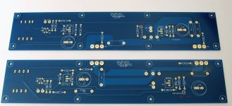
...... so that .... like this?Hi Nicholas -
As Dennis pointed out, yes. One LED is on the negative rail. The PCBs are not exact mirror images. The one with the LED on the negative rail is the one where R2 is not labeled and is placed 'above' C2. Hope that helps.
Attachments

I pulled the source resistor and replaced it with another .47 that tested closer to the actual value. The imbalance between the channels seems better but the channel is still drifty after an hour warming up. And the clarity still opens up every now and then when I have the test pins on the source resistor.
Also novice thought looking at PCB vs. schematic,
I maxed out the Zener diodes at 9.1V (1N4739) based on forum recommendation. Is there any way this could be contributing to the drift/ bias issue?
I am going to pull the board out since it was a nightmare pulling one resistor in place. While it is out I'll check caps.Also check capacitors C1 and C2 and their solder joints.
I have 110 ohm resistors on both gates. Should I bump it up to 200? I have a handful of 3 watt rated 200 and 220 ohm resistors.I also had to increase the gate resistors on my F6 build using SemiSouth JFETs.
Post #6821 on the Pictures of your Pass diy amplifier thread.
Also novice thought looking at PCB vs. schematic,
I maxed out the Zener diodes at 9.1V (1N4739) based on forum recommendation. Is there any way this could be contributing to the drift/ bias issue?
BTW, thank you for your help! I am not out of the woods yet but exciting to be getting close.
Are you saying you are using 9.1V zeners for Z1 and Z2? What resistor values are you using for R7 and R8?I maxed out the Zener diodes at 9.1V (1N4739) based on forum recommendation.
Edit: Also, what are your measured rail voltages? What voltages do you measure across Z1 and Z2?
Yes. When I bought the boards and all my parts (this was a few years ago to be fair) in the original BOM it stated that the spec'd 5.1V diodes didn't provide sufficient voltage to bias properly so a number of builders had opted for 9.1V and no one had encountered any problems doing it that way.Are you saying you are using 9.1V zeners for Z1 and Z2? What resistor values are you using for R7 and R8?
I did not revise the resistor values for R7 & R8 they are 10K.
I am away from home during week but I'll test voltage across the diodes and report back this weekend.
THNX
5V6, 7V5, 8V2, 9V1
all will do, just higher ones giving more twiddly trimpot twiddle
whatever, decrease value of series resistor, to ensure zener actually getting enough juice to give stable voltage
3K3, by memory
all will do, just higher ones giving more twiddly trimpot twiddle
whatever, decrease value of series resistor, to ensure zener actually getting enough juice to give stable voltage
3K3, by memory
@Throw Down : What ZM said. You need to lower R7 and R8. For example, with 9.1V for Z1 and R7=10K there isn't enough current to go through P1=5K and Z1 to keep Z1 stable at its nominal 9.1V value. This allow the bias value to drift with variations in rail voltages (your rails are not regulated).
I am definitely in the twiddly trim pot neighborhood.
I think I get it. The 10k resistor isn't providing enough current relative to 9.1v/5k
So I need to lower resistance (at R7 & R8 ) so it will give me more than 1.82ma.
In my layman terms I have zener diodes that aren't providing stable current for bias/ offset.
Thank you!
I think I get it. The 10k resistor isn't providing enough current relative to 9.1v/5k
So I need to lower resistance (at R7 & R8 ) so it will give me more than 1.82ma.
In my layman terms I have zener diodes that aren't providing stable current for bias/ offset.
Thank you!
Last edited:
Just a follow up. Want to thank everyone for helping me. I checked voltage on zener it was erratic so changed resistor values and got 9.1V stable which enabled me to set stable bias but I still had channel imbalance and it sounded like there was a sock in the port or something. Pulled boards, and found culprit. The solder on electrolytic next to source resistor hadn't bonded to one leg, so it looked good but tapping on the cap, I could see the lead moving through the solder joint. When I was tapping the source resistor with my probes I was probably getting momentary connection of the cap giving the open clear sound I wanted. Interesting that adding/ deleting that one component was such a significant difference in the quality of the sound.
Anyway, all's well that ends well. The sound coming out of the amp is sublime. Working on chassis for my Nutube B1 preamp now.

Anyway, all's well that ends well. The sound coming out of the amp is sublime. Working on chassis for my Nutube B1 preamp now.
Last edited:
- Home
- Amplifiers
- Pass Labs
- F6 Illustrated Build Guide