if you're sure in everything you did mechanically, ignore pin temperature, observe body temperature
or - considering that there is really no need of matching them, replace suspisious one and then recheck
before doing that, back with Iq, rebias later
or - considering that there is really no need of matching them, replace suspisious one and then recheck
before doing that, back with Iq, rebias later
Question on power supply
Understand that for an amplifier like the F6, Mr. Pass recommends around 60,000uF per rail (total of 120,000 uF) for the power supply; this single power supply would be supporting both channels of the amplifier.
In case I want to go dual-mono with 2 transformers and 2 PSU boards, is it still advised to stick 120,000uF total? This would lead to:
- 30,000uF per rail for PSU-1, total capacitance of PSU-1 of 60,000uF
- 30,000uF per rail for PSU-2, total capacitance of PSU-2 of 60,000uF
The power supply boards that I have in hand has space for 4 caps in total (2 caps per rail).
Or ideally I would need to increase the capacitance for each of the PSU boards?
For a dual mono-supply, use 120,000 uF for each channel. Two transformers and two separate PSU boards. So, double the original capacitance.
TungstenAudio,
Thanks for the quick reply. That was what I was fearing 🙂, no shortcuts for power supply capacitance.
Thanks for the quick reply. That was what I was fearing 🙂, no shortcuts for power supply capacitance.
Guys,
When using the LM329 as a voltage reference it appears the resistors used at R7 & R8 can vary. Is that because of rail voltage? If so, do R11 & R12 also vary? Tungsten is using 3.9k at R7 & R8 (26 volt rails). Colin is using 3.3k, I didn’t see a listing of rail voltage. Zen Mod is using 3.6k at R7 & R8 with 130 ohm at R11 & R12 (23 volt rails). What best to use? Rails on my F6 are 26 vdc. Would 3.9k at R7 & R8 be best? If so what about R11 & R12?
Currently I have installed 3.3k at R7 & R8 and 110 ohm at R11 & R12.
I’ve yet to power up either channel but power supply is good to go.
R11 and R12 are gate resistors and don't vary with the use of the LM329.
R7 and R8 are used to feed an appropriate amount of current to the LM329 for it
to develop its nominal 6.9V. The datasheet shows pretty much anything in the
1mA to 10mA range will work quite well. (You might want to have a look
at Fig 9, 10 here:
https://www.mouser.com/datasheet/2/405/lm329-442129.pdf )
Anyway I think your values are fine.
Hello,
I’m having trouble getting bias to stabilize on my f6. Both channels exhibit the same issue. When I first powered up channel B the led lit up normally but the trimmer at P2 didn’t show any change when adjusted. I’m using lm329 as voltage reference with a 3k3 resistor in this circuit. On inspection I found the polarity of lm 329 was incorrect. After correcting I was able to bias the circuit, very slowly until I got .500 mv with close to 0 volts offset. Over the next hour as everything warmed up the bias began to increase, rising to.590 mv. At which point I readjusted bias and offset, again to .500mv and 0 volts. Again I waited for circuit to stabilize but it kept increasing. This was after at least another hour of being powered up. I shut the amp off and revisited the next day. Same results. At this point I started to review this forum for troubleshooting help. Could I have damaged something due to wrong installation of lm329? I’m sure Q3 (170) and Q4 (74) have correct components installed. All solder joints look good. There is 26 vdc going to the channel. But I’m not sure how to proceed.
Please advise
Replace the LM329 with the 5.1v zener and approx. 10K R7, R8 and report back on bias stability.
Attachments
Last edited:
Replace the LM329s with three small green LEDs in series, paying attention to diode polarity. Keep the 3k3 resistors.
The F6 benefits from voltage sources with a negative temperature coefficient. The LM329 is very near zero temp co. The 5.1V zeners may or may not provide sufficient bias voltage.
The F6 benefits from voltage sources with a negative temperature coefficient. The LM329 is very near zero temp co. The 5.1V zeners may or may not provide sufficient bias voltage.
Look for LTL-4231N.
Install like so: Dumb Biasing Mod, applicable to F6 and other Papa Amps. Possibly My Dumbest Idea Yet
Install like so: Dumb Biasing Mod, applicable to F6 and other Papa Amps. Possibly My Dumbest Idea Yet
For a dual mono-supply, use 120,000 uF for each channel. Two transformers and two separate PSU boards. So, double the original capacitance.
To piggy back on my earlier question regarding power supply capacitance that TungstenAudio has clarified (thank you):
If the transformer is relatively large e.g. 500VA, and has 2 secondaries, would it be ok running two separate PSU boards from a single transformer? That means each secondary would be connected to 2 bridge rectifiers of 2 separate but identically configured PSU PCBs.
This way the investment in the extra caps are made, the relief comes in the form of not having to buy additional toroids (at least for the time being). 🙂
yup
just, depending on Gremlins, it can happen that - if you connect each channel to chassis through own bridge-NTC thingie, it can result in hum
in that case, leave just one channel connected that way to chassis
just, depending on Gremlins, it can happen that - if you connect each channel to chassis through own bridge-NTC thingie, it can result in hum
in that case, leave just one channel connected that way to chassis
Noted ZM, and thank you for confirming that it is possible to use a single large toroidal transformer with 2x secondaries to power two PSU PCBs.
Thanks TungstenAudio,
The led string has worked beautifully. I’m getting stable readings from both channels. Whew, what a relief. Next step I really need to be sure I’ve grounded everything well enough.
Here’s what I’ve done: the transformer shield is grounded separately next to the terminal block right on the chassis, the power supply board is grounded through an MS22 inrush limiter as is the primary of transformer, the IEC socket is grounded separately to the chassis, the inputs and outputs are grounded from each channel to a common connection on the power supply. I hope the pictures show this adequately . I’m not sure if this configuration will be quiet. Please advise.
Attachments
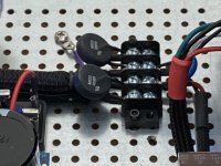
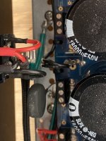
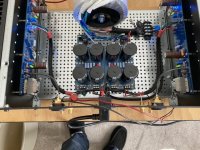
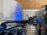
Looks like the purple wire (transformer shield) is grounded well, as is the IEC ground wire. I usually use a CL-60 for the audio ground lift, for its 10 Ohm resistance. I think you’ve got the correct wiring, though.
- Home
- Amplifiers
- Pass Labs
- F6 Illustrated Build Guide