just finished my F6. power supply checks at +-25vdc. meter in photo on positive side. started the left channel first, left meter across 0.47ohm resistor for bias. right meter on output for offset. i have pico's 3 green leds and 4.7k resistor instead of zener and 10 k. turned up variac to 115v slowly, PS measures correctly. turned up p2 5 turns,nothing. turned up some more and offset started to go up . at that point i could turn p1 up and zero it out and turn p2 some more and zero out with p1, at some point offset suddenly ran away to 200mv or better and i shut it off and re zeroed the pots.i was almost 20 turns out on p2 and go no voltage on the meter. mosfets are stone cold, nothing is hot, leds are lit but cant seem to get bias on meter. what else can i check. must be mistake somewhere but i measured everything going in and double checked jfets before soldering. need some test points to troubleshoot. thanks mark
Attachments
![IMG_0247[173].jpg](/community/data/attachments/894/894000-cd2d03690922e94b09d0208a73fb53f1.jpg?hash=zS0DaQki6U)
![IMG_0246[171].jpg](/community/data/attachments/894/894017-303f22112e5604a4ce5512852c6c6e16.jpg?hash=MD8iES5WBK)
![IMG_0248[175].jpg](/community/data/attachments/894/894020-1d8c2a99a4b83e039e1dd4e0e3affc27.jpg?hash=HYwqmaS4Pg)
well, from experience, I wouldn't trust these meters (small DMMs) to keep dead battery in, let alone something more tricky
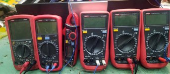
when I'm hysteric chicken (usually doing something new, not sure it'll work), besides placing one DMM to monitor Iq and second to monitor output DC offset, I place two more meters to observe G-S voltage for each mosfet
say that you call your Buddy to bring few meters and sixpack (why should you, you're event organizer ) , then do the same - you'll know where you are with trimpots (Ugs) and you can start trembling when you reach 3V8 and more - only then mosfets will start conducting (soon)
when I'm hysteric chicken (usually doing something new, not sure it'll work), besides placing one DMM to monitor Iq and second to monitor output DC offset, I place two more meters to observe G-S voltage for each mosfet
say that you call your Buddy to bring few meters and sixpack (why should you, you're event organizer
) , then do the same - you'll know where you are with trimpots (Ugs) and you can start trembling when you reach 3V8 and more - only then mosfets will start conducting (soon)Mighty Zen Mod put Simpson meter on g-s of q2 it responded to p2 ran it up to 3 volts. Put meter on g-s of g1 Nada! Would not respond to p2. Got any ideas? Thanks mark
Cheap meter responded to g-s of q2 but nothing happened when across 0.47 resistor. How come that also?
Think I’ll unhook left channel and hook up right channel and see what happens.see if same thing happens. If right channel works it must be q1 mosfet on left channel. If right channel doesn’t work I made same mistake eh ?
if leds are lit, biasing voltage is there,
if mosfet is not shot (having short G to S) , if pot and xformer secondary are OK< biasing voltage must reach the gate and respond to trimpot fiddling
you can check biasing circuits without mosfets ( if you're going to pull them from any reason) ...... trimpot action should lead biasing voltage from 0 to full LED string voltage
take care of mosfet isolation from heatsink ; without mosfets attached to pcb, mid pin to heatsink must show zillion ohms (OL on display)
if mosfets are connected to pcb, all you need is to remove connection between audio GND and chassis, so entire psu is floating (ref to case) then same reading must be for isolation
do not forget to put back connection between audio GND and chassis, be it direct or NTC or cap-bridge-NTC combo
Tested for shorts to heatsink on mosfets before and after soldering to PCb. All okay. Why am I not getting any voltage gate to source on q1 but I am on q2. And no voltage across 0.47 or 0.56 resistors?
Pot must be okay because gate to source voltage on q2 responds to fiddling. But not Q1. Will check trannies secondary for continuity
Does p1 have to be opened up with p2 at the same time? Ie 5 turns each at a time. What I was doing was leaving offset pot off and opening up just bias. Is that what is keeping q1 with no voltage? Wish I was smarter. Insert sad face here.

Does anyone know what the gate source voltage of the mosfets will be when the circuit is at optimum bias? I can turn this past a gate source voltage of 3v7?? . I have only taken it to 3v Maybe I’m not opening the pots enough to get a reading across 0.47
nominally it is 4V
absolute precise value depends of your particular mosfets
so, expect some current showing at source resistors as you're near 4V
absolute precise value depends of your particular mosfets
so, expect some current showing at source resistors as you're near 4V
Mighty Zen Mod, you were totally right. I was just trembling. Nothing wrong with f6, put 4 meters on left channel when mosfets hit 4v bias came up, sitting at 600mv with 0mv offset for an hour now. On to the right channel. Thanks for your wisdom and trick for meters on mosfets. Thank you thank you. Mark
learn from me!!
lack of knowledge what I'm actually doing, I'm always compensating with number of ping machines connected to amp!!
so, just part of my ping machines, and I'm always happy
lack of knowledge what I'm actually doing, I'm always compensating with number of ping machines connected to amp!!
so, just part of my ping machines, and I'm always happy
Attachments
locally
have Vendor with decent prices, due to direct import from Uni-T
accidentally, we had Group Buy on Baby DiyA ...... we almost got dedicated logo on them , but it was too late for idea , already purchased
I don't care for that, anyway
have Vendor with decent prices, due to direct import from Uni-T
accidentally, we had Group Buy on Baby DiyA ...... we almost got dedicated logo on them , but it was too late for idea , already purchased
I don't care for that, anyway
Mighty Zen Mod, F6 is playing music but q1 mosfet on left channel is running 18 to 20 degrees hotter than the others. I used mica and grease with split washers and snugged down. Heatsink was sanded for high spots at threads.if I use 6l6’s advice on pin 2 no hotter than 150 F measured at the PCb I can’t run .600mv bias I have it dialed back to 540mv to get at 150 degrees.any thoughts? Mosfet body isn’t that hot just the pin. Heatsink is 110 F even at .600mv bias
well, if DC offset is proper, logic dictates that dissipation of upper and lower mosfet is the same, simply as they are part of one current path, each having same voltage across
if one mosfet is hotter than other, blame thermal interface .......
I mean - besides blaming Pa - he's responsible that you're playing with amps, instead of hanging in some Pub, drinking, as all proper Men are doing
fact that you're not seeing culprit ......... let's just say that you still didn't saw it , but you will
practically - do not bother with exact number, just look that all 4 are having same temperature, as they must
- Home
- Amplifiers
- Pass Labs
- F6 Illustrated Build Guide