
Looking for .025 ohm 1% resistors to continue experiment - Should they be non inductive?
Thanks
Bob
Thanks
Bob
I don't think you really need the mounting flanges on the daughter boards. That will also add to the cost due to more than 5 points of routing.
Bob,Looking for .025 ohm 1% resistors to continue experiment - Should they be non inductive?
Thanks
Bob
I see this
LVR03R0250FS70 Vishay/Dale | Mouser
I don't think you really need the mounting flanges on the daughter boards. That will also add to the cost due to more than 5 points of routing.
I chatted with the board house on this. They dismissed any difficulty or high cost associated with it, and to essentially treat as a square board measured from the edges. It was CRTs idea to bolt on (and he has done the most work, me I just complain a lot about small things) and I think a good one. Probably a Jensen will not fall off, but I suspect an Edcore Xs-4400 like Generg uses might. Good precaution. I will start seperate thread soon once i am close to sending gerbers out for production.
Last edited:
They are nice but, an LVR05R025 will radiate heat better, stay cooler and has 1/2 the Tc of the 3W in that R range.

So, with Nelson's approval, I will try to post something close to the following for sale after a prototype is made and built.
It will use a daughter card concept to add in a Onetics or Jensen transformer, or allow a Perfboard to be mounted on the 2x10 2.54 Male pins to roll your own transformer onto it.
It will have all four pots and will be based on the F6 Second Harmonic. If one wants a simpler versions than jumpers need to be put in place for it. It may not be for everyone, but it will reach market, pending approval and I don't get hit with a snowplow or something.
Pandora's box for transformer tweaking......😀 beautiful!
Heat dissipation is not an issue for such a low resistance. The idle power will be Ibias^2*R. For Ibias=1.5A, and R<0R44, the power will be less than 1 watt.
They are nice but, an LVR05R025 will radiate heat better, stay cooler and has 1/2 the Tc of the 3W in that R range.
DC Quiecent Pd is not the issue I would be concerned with here. When virgins carved these resistors from unubtainium etc. etc. they were intended for people with ultra linearity performance in mind. The temperature variation of the Rsource will cahnge it's degeneration properties with signal excursion. More so with higher TcR. More so with less radiating mass. Search out "memory distortion". That is some of the "magic" surrounding the metal strip resistors.
I'm not going to argu the deminousing returns involved in this engineering logic but, just sayin 😀
I'm not going to argu the deminousing returns involved in this engineering logic but, just sayin 😀
Bob,
I see this
LVR03R0250FS70 Vishay/Dale | Mouser
Thanks Tea-Bag
Missed them first time through Mouser
per fig's post (thanks)
I also found these
5W 0.025 ohm .025 ohm Wirewound Resistor Dale LVR05R0250FR55: In Stock Buy Now - West Florida Components
I don't know anything about the company
The also have an interesting collection of capacitors
Best
Bob
I also found these
5W 0.025 ohm .025 ohm Wirewound Resistor Dale LVR05R0250FR55: In Stock Buy Now - West Florida Components
I don't know anything about the company
The also have an interesting collection of capacitors
Best
Bob
.....PCB rev 4.0 😉
Alex-Love just loverly... any chance you could post the files for this so I make a few and retire my vero ? cheers ....
Oops, the correct equations are not as simple as I presented. I have corrected equations and graphs for the open-loop case, but closing the loop is more complicated. Push-pull will complicate things further.
flocchini: No degeneration and no Zen Pots gave you the simplest design and the least number of parts. Did you hear anything like your diyF6 before? lhquam had reported in a much earlier post that his Teaser-6 reminded him of the sound of a vacuum tube amplifier. He did not qualify it as based on a triode or pentode output. What was your impression? Does it remind you of a particular amp?Update 2
First of all resistance measurements I gave in previous post were high - forgot to subtract lead resistance.
Took out the pots and R13, R14 to calibrate my ears with zero resistance on SSs
Listened for a couple hours and then did R13 =0 and R14 = .05 ohms. After that I reversed R13 and R14. To my ears with R13 =0 and R14 = .05 soundstage was forward. Reversing the resistors moved it back. When Nelson said a small amount of resistance added to SSs I think he meant it. It doesn't take much to change things.
I'm back to no degeneration - it sounds best to my ears and with the other amps in my tri-amp.The voices sound really natural - there is good slam and detail. I would love to hear F6 with a 100dB system like LaScala
Again thanks to all that have helped - may learn how to take some measurements with the Mac.
buzzforb - If no boards become available I will hand wire the Jensens.
Best
flocchini: No degeneration and no Zen Pots gave you the simplest design and the least number of parts. Did you hear anything like your diyF6 before? lhquam had reported in a much earlier post that his Teaser-6 reminded him of the sound of a vacuum tube amplifier. He did not qualify it as based on a triode or pentode output. What was your impression? Does it remind you of a particular amp?
Antoinel
Based on my first impressions I would say it has the bass punch of my Aleph 30 and the liquidity of an F3. I also think it is very similar to the hybrid F4 (F4 with interstage transformer) headphone amp I put together.
Currently I am using it as the midrange amp (250 -6000 Hz) in my system driving PHl 1120s. The Aleph is driving the low end because of it has twice the gain. The F3 is on the high end driving Raven 2s. A really nice combo
I have never used tube amps so I can't provide input
Best
Bob
Tea
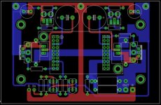
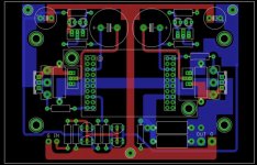
first one ( se.jpg ) is original, while second one (see.jpg ) is edited
difference is in point where you're going to solder main gnd from PSU
I moved it to mid bottom , that way securing that sig gnd is not poluted with speaker soaking
first one ( se.jpg ) is original, while second one (see.jpg ) is edited
difference is in point where you're going to solder main gnd from PSU
I moved it to mid bottom , that way securing that sig gnd is not poluted with speaker soaking
Attachments
Tea
first one ( se.jpg ) is original, while second one (see.jpg ) is edited
difference is in point where you're going to solder main gnd from PSU
I moved it to mid bottom , that way securing that sig gnd is not poluted with speaker soaking
Thanks. Makes sense now. Editing was too good for me to notice 🙂
Need to get the PSU stuff labeled too.
- Home
- Amplifiers
- Pass Labs
- F6 Amplifier