I'll leave the technical mumbo jumbo o the smart people, but when building the BA3, I asked Nelson whether or not going balanced would negate the trimming i had done with P3(yielding higher 2K harmonics) would be nulled by balanced implementation. If i remember correctly, he stated that although it would occur, the character of the independent halves would still remain to a certain degree. I say this to answer the questions about whether or not the changes would be nulled by OLF. Nelson told us the importance of the sweet spot, showed us how to do it with P3. We got some help from ZM with Zen Pot on setups like this and J2. Anything else is going to take building and testing, not speculating. Go blow some @$!% up and lets have some fun.
The Zen Pot idea would be considered local feedback I would think. But, what do I know
in some cases yes , in some cases not
speaking strictly about F6 and MR's amp - with pot you're varying degree of either direct AC modulation , or AC degeneration (indirectly influencing AC modulation)
......
example :
Attachments
JLH
Thorsten Larsen
It was lower position.ya'll remember advices for venerable JLH amp , and choosing output with higher beta to upper(?) position ?
Thorsten Larsen
Zen Pot
Fine people: We have not been on the same page regarding " Zen Pot". I hope my post will clear this inadvertent confusion. Please consult the attached file ZenPot.pdf.
The following puts us all on the same sonic wavelength.
I'll leave the technical mumbo jumbo o the smart people, but when building the BA3, I asked Nelson whether or not going balanced would negate the trimming i had done with P3(yielding higher 2K harmonics) would be nulled by balanced implementation. If i remember correctly, he stated that although it would occur, the character of the independent halves would still remain to a certain degree. I say this to answer the questions about whether or not the changes would be nulled by OLF. Nelson told us the importance of the sweet spot, showed us how to do it with P3. We got some help from ZM with Zen Pot on setups like this and J2. Anything else is going to take building and testing, not speculating. Go blow some @$!% up and lets have some fun.
Fine people: We have not been on the same page regarding " Zen Pot". I hope my post will clear this inadvertent confusion. Please consult the attached file ZenPot.pdf.
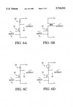
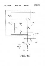
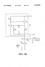
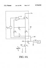
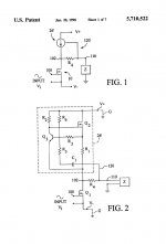
- Figure 1 shows a constant current source loading a "FET" gain stage. This [Prior Art] was the practice of Mr. Pass in some of his amps
- Figure 1a shows a Modulated Current Source loading the same "FET" gain stage. The addition of R and C to the basic circuit of Figure 1 enabled this modulation [Invention] . Nelson S. Pass was granted US Patent # 5,710,522. The resistor R is not Zen Pot.
- Figure 2 shows a simplified diagram of the front end [FE] of F5. I hand copied it from the 2012 F5 Turbo article on www.firstwatt.com. Zen Pot is component P3 [200 Ohms plus other resistors]. The specific importance of P3 follows [cut and pasted from the article]
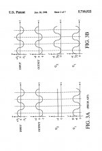
"One thing that many will appreciate is the addition of P3, which due to inattention on my part was not public until recently. It allows the adjustment of the distortion character between complete nulling of the second harmonic distortion to an arbitrary ratio of second to third harmonic. It definitely alters the sound, and reaffirms that things going on below 0.1% are audible. In anycase, you can adjust it to taste. Here is what the waveform looks like when the second harmonic is allowed to be about....
The following puts us all on the same sonic wavelength.
- The proposed physical location [and sonic value] of P3 in F6 and its clones belongs in its FE circuit and not in the output stage.
- Does anyone wish/need to practice the teaching of US 5,710,522 in the output stage of F6 and its clones? The output configuration of F6 looks promising like in those of Figures 1, 1a.
- No relation between the resistor R in US 5,710,522 [Figure 1a] and Zen Pot [Figure 2]
I hope to have redeemed myself [mea culpa !] with this note.
Attachments
Last edited:
I hope that we cleared the frustrating confusion. The body of US 5,710,522 may show the significance of resistor R [Fig 1a] regarding the management of distortion. This is an example of me practicing diyaudio therapy by proxy.Same goal, different tool. Trust me
Last edited:
Thanks buzzforb. I fully agree with you regarding the proposed location and significance of Zen Pot in F6 and its clones.You misunderstood. Zen pot in F6 accomplishes same goal as P3 in F5. Same gola, different tool.
I hope that we cleared the frustrating confusion. The body of US 5,710,522 may show the significance of resistor R [Fig 1a] regarding the management of distortion. This is an example of me practicing diyaudio therapy by proxy.
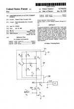
buzzforb. The following pertains to US Patent #5,710,522; Fig 1a in my ZenPot.pdf file of an earlier post. It was filed July 15, 1996. Add 20 years life to it. Will expire in later than July 15 2016. It is alive and protected!
Amplifier having an active current source
Abstract The present invention is a single-ended Class A gain stage amplifier consisting of an active current source. A feedback path from an output node of the amplifier senses the direction and magnitude of the current going through a load coupled to the output node. The feedback path varies the output of the active current source in accordance with the sensed load current. By so doing, the efficiency of the amplifier of the present invention can be doubled as compared to prior art amplifiers operating in Class A mode. In addition, the present invention amplifier exhibits lower signal distortion.
Last edited:
Buzz: That is exactly right.
In the F5, the P3 pot trims the two feedback networks to adjust the open-loop gains of the upper and lower halves of the amplifier. Making the open-loop gains equal at operating point nulls the 2nd harmonic.
In the F6, the Zen pot adjusts the effective degeneration resistance of one output FET, thus modifying the open-loop gain of one FET relative to the other.
Same goal, different tool. Trust me
..... exhibits lower signal distortion. [/B]
one thing , which I didn't saw mentioned , is that sensing the load , it sense impedance variations , thus not behaving as usual sissy SE output .....
btw. there were numerous posts and threads regarding setting AC gain of Aleph CCS , along with several attempts of various members - trying it as plain (non modulated ) , thus non-Aleph CCS
conclusion is that majority of Greedy Boyz prefer 50% AC gain point , some prefer different amount , some like non-Aleph CCS , some simply hate it.
Last edited:
......
regarding your F6 wannabe -did you already tried some amount of simplest , crude SE bias addition ?
 Save that for when i get back from vacation
Virtual consensusone thing , which I didn't saw mentioned , is that sensing the load , it sense impedance variations , thus not behaving as usual sissy SE output .....
btw. there were numerous posts and threads regarding setting AC gain of Aleph CCS , along with several attempts of various members - trying it as plain (non modulated ) , thus non-Aleph CCS
conclusion is that majority of Greedy Boyz prefer 50% AC gain point , some prefer different amount , some like non-Aleph CCS , some simply hate it.
F6 Decoded
Please consult the attached file ConceptualF6.pdf.
The signal phases in the schematic of Conceptual F6 in Post #1 are correct as shown. This schematic is the invention US 5,710,522; albeit a much simpler and brilliant improvement.ZM has been nagging me for information on the F6. I have a very nice
sounding prototype, but the design and the article that accompanies it
have some details remaining.
However, I can afford to put out this teaser:
Please consult the attached file ConceptualF6.pdf.
- The bottom portion shows the schematic of the Aleph Current Source. Follow the sine wave squiggles where I indicated by the lightning arrows. The important signal squiggles are at the gates of Q1 and Q2. They are in phase.
- The top part shows the relevant part of the schematic in Post #1. The phase of the signals at the gates of the output JFETs are exactly like those in the Aleph Current Source; or in-phase.
Attachments
it's more like - F6 , Antoinel-ed
re-read the patent
it's ..... well , patented
http://www.pat2pdf.org/patents/pat5710522.pdf
re-read the patent
it's ..... well , patented
http://www.pat2pdf.org/patents/pat5710522.pdf
Attachments
-
 pat5710522_Page_10.jpg241.3 KB · Views: 97
 -
 pat5710522_Page_09.jpg216.7 KB · Views: 109
 -
 pat5710522_Page_08.jpg36.5 KB · Views: 108
 -
 pat5710522_Page_07.jpg36.3 KB · Views: 105
 -
 pat5710522_Page_06.jpg35.7 KB · Views: 99
 -
 pat5710522_Page_05.jpg33.3 KB · Views: 276
 -
 pat5710522_Page_04.jpg35.4 KB · Views: 281
 -
 pat5710522_Page_03.jpg52.4 KB · Views: 275
 -
 pat5710522_Page_02.jpg39.9 KB · Views: 281
 -
 pat5710522_Page_01.jpg85.4 KB · Views: 285
Last edited:
...... make a difference between current and voltage phase ;
besides that - there is no output current sensing anywhere in F6 , at least not in Aleph style
besides that - there is no output current sensing anywhere in F6 , at least not in Aleph style
Attachments
Last edited:
US #5,710,522 belongs exclusively to Nelson S. Pass. F6 is US 5,710,522. Mr. Pass has the legal right to prevent others from practicing it. It means that commercial copycats can only practice the out-of- phase but not the in-phase signal drives to the output JFETs.
I read the subject patent many moons ago. The 3 vectors which led to this current revelation clicking now are:
- A patent is a legal and business [focus] tool. The astute business inventor effectively uses the granted patent during the 20 years begining with the filing date to further [capitalize on] his/her attendant business endeavors.
- The fascinating Zen Pot post discussions. It said look again at the patent
- I am a diyAudio member. If not somebody else will have made the connection; or disclosed by Mr. Pass.
Bullet #1 hints where Mr. Pass will go to with F7 etc..
Last edited:
- Home
- Amplifiers
- Pass Labs
- F6 Amplifier