you can bet that Papa did look at THD spectra and spoil symmetry , to achieve what he want , if he want
So What. Big Deal.
(Actual quote from the movie Buckaroo Bonzai: Across the 8th Dimension)
I discovered that the transformer I used has been discontinued. We will
have to find another. And none of these $50 jobbies.
😎
(Actual quote from the movie Buckaroo Bonzai: Across the 8th Dimension)
I discovered that the transformer I used has been discontinued. We will
have to find another. And none of these $50 jobbies.
😎

What if that upper devices job (the source follower) is to only null/cancel harmonic distortion?
I could imagine doing something like that.
I could imagine doing something like that.
Last edited:
yup , exactly
I already explained iteration called Silencer
whatever you throw on input - there is silence on output

I already explained iteration called Silencer
whatever you throw on input - there is silence on output
yup , exactly
I already explained iteration called Silencer
whatever you throw on input - there is silence on output
Just not sure how to reduce or remove the fundamental so only the harmonics are removed
Will this blow up?
Had a similar thought, a little simpler, driving one device only, made the other Aleph ccs (modulated), using depletion mode devices for self biasing, and the feedback terminates at the JFET's input.
If so, then Zen Mod's suggestion of using Enhancement and Depletion N-Jfets [with in-phase driveto their gates] is a possibility. Granted the two devices are exact opposites in characteristics; such that a high symmetry in operation is obtained. Loop feedback will correct for residual asymetry.I think maybe Papa has hit a roadblock on his design and is looking for ideas from us. 😀
Haha. Very clever way of interrogating someone.I think maybe Papa has hit a roadblock on his design and is looking for ideas from us. 😀
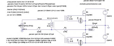
I realize that this is an incomplete circuit (no input buffer, and no bias circuits), but it demonstrates the drive of the output FETs from the transformer. I have no idea what inductances should be used for the transformer. In this simulation I used a 1:1 winding ratio.
watts Thd
1 0.039940%
5 0.023063%
10 0.017839%
15 0.018988%
25 0.032031%
watts Thd
1 0.039940%
5 0.023063%
10 0.017839%
15 0.018988%
25 0.032031%
Attachments
What if you have positive feedback on the source follower to increase harmonics so they cancel out with the common source output?
I realize that this is an incomplete circuit (no input buffer, and no bias circuits), but it demonstrates the drive of the output FETs from the transformer. I have no idea what inductances should be used for the transformer. In this simulation I used a 1:1 winding ratio.
watts Thd
1 0.039940%
5 0.023063%
10 0.017839%
15 0.018988%
25 0.032031%
Please reverse the phase of the transformers above to be like that in thread #1. We look forward to your comparative results.
34 pages, but no one has asked the most important question:
Will it drive F4?

Really?This is not misdirection. Try it both ways and see.
😎
In any case, ZM corrects me. JT123-FLPCH is still available.
This is obviously one of those days where the cosmos is playing with me.
Lucky I have ZM around to play Jester.

This is obviously one of those days where the cosmos is playing with me.
Lucky I have ZM around to play Jester.
- Home
- Amplifiers
- Pass Labs
- F6 Amplifier