I’m not good at explaining theory but a choke is a reactive component with no resistive losses. A choke should give better regulation since it stores energy and has less losses than an bunch of resistors for a power supply filter. Inductors in the power supply are good at reducing ripple. Again this isn’t always the case but in a lot of cases. I’m not fully qualified like the pros here but I’m sure someone will give a better explanation than I did.
Just building on the differences between CRC vs CLC approach:
1) PS Stability
- Selection of L values is very important for CLC as you could theoretically build an unstable power supply, typically you need rather big inductors for the required range
- While CRC is wasting energy, it also makes it unconditionallt stable
2) Magnetic influence
- Inductors in CLC could have magnetic effect on the rest of the circuit
- CRC does not have this effect obviously
3) Ripple reduction (when designed with right parameters)
- CLC is a 2nd order low pass filter: eg 12 db slope
- CRC is a 1st order: eg 6 db. Hence CLC could suppress PS ripple theoretically better but again requires a more careful consideration
So my humble 2 cents: very difficult to call out singular best approach, one needs to consider multiple dimensions for a PS
Hope it helps, (well nothing conclusive so probably not, but still 🙂)
Thanks S. Do you have any sources for a formula for calculating how big the inductor needs to be?
Thanks S. Do you have any sources for a formula for calculating how big the inductor needs to be?
Try this 🙂
PSUD2
Yes, That is a nice program to try out different C L combinations, and other power supply configurations as well.
To get you a brief overview:
Low Pass Filter Calculator - ElectronicBase
You can also check this for the theory.
Hope it helps
To get you a brief overview:
Low Pass Filter Calculator - ElectronicBase
You can also check this for the theory.
Hope it helps
My F4 Build
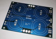
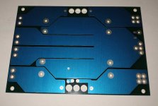
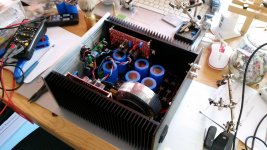
Sharing some pics. Just got my Mini Dissipante chassis from Hifi2000. They did a nice job on a customized faceplate🙂
Another pair of F4’s coming alive soon😉
Sharing some pics. Just got my Mini Dissipante chassis from Hifi2000. They did a nice job on a customized faceplate🙂
Another pair of F4’s coming alive soon😉
Attachments
Sharing some pics. Just got my Mini Dissipante chassis from Hifi2000. They did a nice job on a customized faceplate🙂
Another pair of F4’s coming alive soon😉
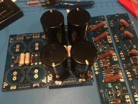
You've built a great RF-reveiver with those foil-resistors >1cm away from PCB with a "loop"-antenna... It's better to form the leads with two fine pliers so that the leads are as short as possible.
You've built a great RF-reveiver with those foil-resistors >1cm away from PCB with a "loop"-antenna... It's better to form the leads with two fine pliers so that the leads are as short as possible.
I am planning on building a "maxed out" F4 with the z-foil resistors too. Nice to see an example and get some feedback on how best to install.
Preamp for F4
Another preamp that works well with the F4 is the S5 Electronics K-PL kit.
This was my first tube build and it was pretty easy. Needs a 200v power supply and 6.3v for filaments. Antek has a dual 140v and dual 6.3v secondaries.
I used a 175v version, but had to drop the voltage by ~40v. The 140v will get you closer with less fuss.
K-PL uses a 5670 triode tube, however member (audiowise) recommended the 6922 with a cathode cap. Said 6922 will halve the output impedance. I will be trying th 6922 as well with a 60uF MKP. As-is it sounds pretty good.
I upgraded the main board parts for $25.
Price is right. Basic Bud chassis and other parts came to under $200.
It is my opinion that it sound way better than the price suggests.
S5 K-PL
If I build this crippled version of the F4 to drive some headphones, do I really need R47 source resistors? What's the lowest value I could probably get away with in the case of a single n/p output pair?
Also, I'm considering building it with FQA19N20/FQA12P20 outputs, but that shouldn't make a difference in regard to the source resistor choice I suppose.
Also, I'm considering building it with FQA19N20/FQA12P20 outputs, but that shouldn't make a difference in regard to the source resistor choice I suppose.
Attachments
you wanna scale it up , or scale down?
what are the goals , regarding dissipation and output power?
and presumed load is ( Ohms) ?
what are the goals , regarding dissipation and output power?
and presumed load is ( Ohms) ?
While it may be fun modifying something which works perfectly like F4, and turning it into something which may or may not work, i would humbly suggest to simply build something which Nelson graciously already published, like ACP+.
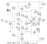
FIRST WATT
FIRST WATT
The goal is a scaled down F4 with fewer output pairs, hence I arrived at the crippled F4.
The F4 headphone schematic as seen in post #3026 F4 power amplifier may be what you're referring to, ZM? I still prefer the bigger output FETs.
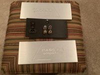
I already have a case and PSU from my Aleph H build (see attachment), and a 18VAC 250VA transformer, plus a pcb and all the parts for the F4. If I read my notes correctly, the Aleph H currently conveniently dissipates something like 20W per channel, so the +\-22V @0.5A each should fit the current heatsinks nicely.
The amp will drive a HE6 headphone, with a ruler flat 50R impedance. The F1J drives them nicely. According to innerfideliy, the HE6 takes 1.018Vrms to reach 90dB SPL. Vrms=Vpk*2^-.05 and thus Vpk=1.44V. Ipk=Vpk/R and thus Ipk=30mA, roughly. With 6dB of headroom we're at almost 100mA.
The F4 headphone schematic as seen in post #3026 F4 power amplifier may be what you're referring to, ZM? I still prefer the bigger output FETs.
I already have a case and PSU from my Aleph H build (see attachment), and a 18VAC 250VA transformer, plus a pcb and all the parts for the F4. If I read my notes correctly, the Aleph H currently conveniently dissipates something like 20W per channel, so the +\-22V @0.5A each should fit the current heatsinks nicely.
The amp will drive a HE6 headphone, with a ruler flat 50R impedance. The F1J drives them nicely. According to innerfideliy, the HE6 takes 1.018Vrms to reach 90dB SPL. Vrms=Vpk*2^-.05 and thus Vpk=1.44V. Ipk=Vpk/R and thus Ipk=30mA, roughly. With 6dB of headroom we're at almost 100mA.
Attachments
then make it s you wish
looking at FQ datasheet, I believe you can make it without source resistors ..... but with them , you'll have lesser difference both in Iq and output offset , cold vs. hot
looking at FQ datasheet, I believe you can make it without source resistors ..... but with them , you'll have lesser difference both in Iq and output offset , cold vs. hot
K-PL uses a 5670 triode tube, however member (audiowise) recommended the 6922 with a cathode cap. Said 6922 will halve the output impedance. I will be trying th 6922 as well with a 60uF MKP.
This info was incorrect. 6922 is not pin compatible with 5670.
Hi,
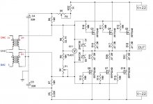
I am building F4 amp. I have dual mono ad1865 DAC with output transformers doing I/V conversion.
How to connect my dac to F4 to skip AC C1,C2 coupling caps?
Could guys help with this? Do you see any drawback of such approach? Which schematic is correct?
I am building F4 amp. I have dual mono ad1865 DAC with output transformers doing I/V conversion.
How to connect my dac to F4 to skip AC C1,C2 coupling caps?
Could guys help with this? Do you see any drawback of such approach? Which schematic is correct?
Attachments

- Home
- Amplifiers
- Pass Labs
- F4 power amplifier