I've quickly come to the conclusion that I would go mentally mad and financially broke while my spare parts bins would turn to spare parts rooms if attempting passive bi-amping.
The active option is still on the table.
The active option is still on the table.
I would think that “very soon” might may perhaps possibly mean “this year sometime if everything works out.”
Damn, was hopeful that the delay from "should be done in October" meant that we were closer. Thanks for the more accurate time frame correction, appreciate it.
Very soon means that I am actively working on it. Would have been done by
now, but I found a flaw in the design...
now, but I found a flaw in the design...
.... Would have been done by
now, but I found a flaw in the design...
Blame ZM


Just blame him for everything.
Like if you get cold solder joint and your amp doesn't work, it is Zen Mod's fault.
Bloody Zen Mod.
Like if you get cold solder joint and your amp doesn't work, it is Zen Mod's fault.
Bloody Zen Mod.

Thanks for the update Nelson. I'll just keep re-reading articles about the xvr1 and fantasizing to pass the time...
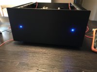
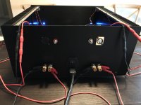
After my dad lusting over my M2x for months I just gave it to him for Christmas. Since I had an open space on the shelf I decided to build the F4 and damn this one is dope. Me like!!
Attachments
I noticed your toroidy transformer...there’s a dude asking questions about them in the M2X thread post 2731. Maybe you could follow up with him.
Must be you have a nice preamp.
Must be you have a nice preamp.
Last edited:
I noticed your toroidy transformer...there’s a dude asking questions about them in the M2X thread post 2731. Maybe you could follow up with him.
Must be you have a nice preamp.
I’ll check out the post
I’m using a canary ca900
After my dad lusting over my M2x for months I just gave it to him for Christmas. Since I had an open space on the shelf I decided to build the F4 and damn this one is dope. Me like!!
Hey there, I've been thinking about building a new power supply for my F4s. I'm currently using the standard board from the store. Is there a place I can read about the version you're using? Could you say a bit about how they compare?
Thanks so much.
Hey there, I've been thinking about building a new power supply for my F4s. I'm currently using the standard board from the store. Is there a place I can read about the version you're using? Could you say a bit about how they compare?
Thanks so much.
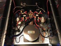
I'm terrible at explaining things but I'll give a better explanation when I'm off work. Essentially I followed the same schematic as the store PSU but instead of resistors I used an inductor to create a CLC. The caps are 82,000uF each so I'm using 164,000uF per rail. The large grounding busbar is for home doorbells or other home needs. I cant comment on how an F4 sounds between the store PSU and the one I used but I will say with the more capacitance, the noise floor is MUCH lower. My Aleph J is pretty silent on 98db speakers using the store PSU but this one I have to physically put my ear on the cone to hear anything.
I'm terrible at explaining things but I'll give a better explanation when I'm off work. Essentially I followed the same schematic as the store PSU but instead of resistors I used an inductor to create a CLC. The caps are 82,000uF each so I'm using 164,000uF per rail. The large grounding busbar is for home doorbells or other home needs. I cant comment on how an F4 sounds between the store PSU and the one I used but I will say with the more capacitance, the noise floor is MUCH lower. My Aleph J is pretty silent on 98db speakers using the store PSU but this one I have to physically put my ear on the cone to hear anything.
Thanks, I'd really appreciate that. I keep looking at everyone's power supplies and wondering how they'd compare. I did build mine with a large capacitor reservoir... 4 x 180,000uF (Panasonic TS-UP) + a 50uF motor run foil bypass cap per rail. Thanks again for posting...
Thanks, I'd really appreciate that. I keep looking at everyone's power supplies and wondering how they'd compare. I did build mine with a large capacitor reservoir... 4 x 180,000uF (Panasonic TS-UP) + a 50uF motor run foil bypass cap per rail. Thanks again for posting...
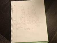
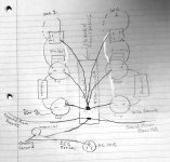
Let me know if this doesn’t make sense but this is my PS setup. And like always, use your light bulb tester. I don’t think I missed anything but it was a long day at work and I’m sure someone will chime if I did miss something
Attachments
Let me know if this doesn’t make sense but this is my PS setup. And like always, use your light bulb tester. I don’t think I missed anything but it was a long day at work and I’m sure someone will chime if I did miss something
Thanks, much appreciated... that looks perfect.
Could you (or anyone else) mention why having a choke in between the cap banks is more desirable than the more standard resistor approach? Just trying to understand the circuit a bit better. Thanks again.
Let me know if this doesn’t make sense but this is my PS setup. And like always, use your light bulb tester. I don’t think I missed anything but it was a long day at work and I’m sure someone will chime if I did miss something
Attachments
Thanks, much appreciated... that looks perfect.
Could you (or anyone else) mention why having a choke in between the cap banks is more desirable than the more standard resistor approach? Just trying to understand the circuit a bit better. Thanks again.
I’m not good at explaining theory but a choke is a reactive component with no resistive losses. A choke should give better regulation since it stores energy and has less losses than an bunch of resistors for a power supply filter. Inductors in the power supply are good at reducing ripple. Again this isn’t always the case but in a lot of cases. I’m not fully qualified like the pros here but I’m sure someone will give a better explanation than I did.
- Home
- Amplifiers
- Pass Labs
- F4 power amplifier