The calculation goes 1.59A * 2 = 3.18A peak
3.18 * 3.18 *8 = 80 watts peak Class A into 8 ohms
and 40 watts peak into 4 ohms
😎
I know this is a very old post.
Papa are you indicating that the Firstwatt F4 was biased at 1.59A?
why is that so important?
have to carve it in Stone ?

Not so important, just an interesting fact that I wasn't aware of, if true.
Nice one. That is what I always thought.IIRC F4 service manual mentioned 430mA per pair, so 1.29A.
Papa may have been responding to someone saying "it will be Class AB into 4 Ohms
 ", and was just suggesting that in diy, you can build it anyway you want to get around these problems.
Last edited:
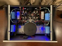
I decided to do some changes to 1 of my F4s during the Holidays. First I bumped up the PS capacitance with four 68,000 big caps, then added four 47uf decoupling caps and finally replaced the Pi resistors with chokes. Also replaced the 15ga wiring with 9ga wiring. It is interesting to compare this one with the stock build F4. While changes to the sound are subtle I am quite happy with the results. The bottom end is more defined & detailed and the overall sound of the amp is more relaxed.
Attachments
I decided to do some changes to 1 of my F4s during the Holidays. First I bumped up the PS capacitance with four 68,000 big caps, then added four 47uf decoupling caps and finally replaced the Pi resistors with chokes. Also replaced the 15ga wiring with 9ga wiring. It is interesting to compare this one with the stock build F4. While changes to the sound are subtle I am quite happy with the results. The bottom end is more defined & detailed and the overall sound of the amp is more relaxed.
Nice one.
I decided to do some changes to 1 of my F4s during the Holidays. First I bumped up the PS capacitance with four 68,000 big caps, then added four 47uf decoupling caps and finally replaced the Pi resistors with chokes. Also replaced the 15ga wiring with 9ga wiring. It is interesting to compare this one with the stock build F4. While changes to the sound are subtle I am quite happy with the results. The bottom end is more defined & detailed and the overall sound of the amp is more relaxed.
Nice indeed,
It is always difficult to resist the urge to make multiple changes and "general clean-up's" at once. But it does make the conclusions on what worked well and what didn't a lot more fuzzy 🙂
I also experienced my first F5 monos to be very relaxed - in fact they were so relaxed that it seemed they had entered retirement... 🙄
Luckily this went away when I replaced the (high current) PSU chokes with resistors.
😎
Too little time too many projects - next up is either my set of (balanced) F4's or an UGS-Upgrade.... or/and PeeCeeBeeV4H - Good to be spoiled for choice!
It's likely to be the F4's first - Don't mind a little heat, its cold here in winter - and winter is long...!
However, that will leave me with another project / challenge - a pre-amp capable of delivering the needed output sving.
- recommendations and experiences would be most welcome
Just realized that my AR LS2B pre will happily deliver 60vrms, that will do for sure....
Should I get nervous ticks about the non-balanced nature of the balanced output, then there is always the pumpkin 😉
Adding Switchable Bias
Wanted to see if I had a reasonable idea to allow for variable bias settings on my F4 build I’m planning. The basic idea is to have a low bias setting for a low power setting to keep circuits warm, a mid bias for normal listening, and a high bias room heater mode for getting the most outta the amp.
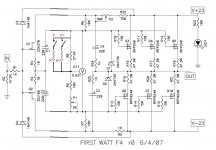
I didn’t want to add a mechanical switch to the basic F4 circuit, so I used LDR optocouplers as the means to change resistance of R9. I also wanted to make sure DC offset stayed at 0 for each bias level so I used another LDR to change the R22 resistance. The specific LDR is the NSL-32SR2.
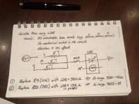
I will need to add a regulated 5V power source for this circuit and need a shorting 4-pole 3 position selector switch (based on a comment from Nelson to an earlier post trying to do variable bias as well). Sorry for the handwritten description... I drew this at breakfast while on a trip. What an opening for comments about a different type of trip... 😉😎😉:cool
The target bias settings on the note attached are not finalized until I go thru the biasing of my build, but gives the basic idea of where I’m headed. I’ve borrowed ideas on the LDRs from posts on the Lightspeed volume control and the Zen Mod approach to use LDRs. The F4 circuit is not included and is only indicated by a hard to read F4* indication. And finally, the ideal resistance range for R9 and R22 has not optimized until I’ve been through biasing the basic circuit. For the R9 position, the LDR and a companion resistor is in series to get the approximate resistance range while for R22, the LDR has a companion resistor in parallel.
Let me know if this will work and any suggestions for improvements...
Cheers
Rob
Wanted to see if I had a reasonable idea to allow for variable bias settings on my F4 build I’m planning. The basic idea is to have a low bias setting for a low power setting to keep circuits warm, a mid bias for normal listening, and a high bias room heater mode for getting the most outta the amp.
I didn’t want to add a mechanical switch to the basic F4 circuit, so I used LDR optocouplers as the means to change resistance of R9. I also wanted to make sure DC offset stayed at 0 for each bias level so I used another LDR to change the R22 resistance. The specific LDR is the NSL-32SR2.
I will need to add a regulated 5V power source for this circuit and need a shorting 4-pole 3 position selector switch (based on a comment from Nelson to an earlier post trying to do variable bias as well). Sorry for the handwritten description... I drew this at breakfast while on a trip. What an opening for comments about a different type of trip... 😉😎😉:cool
The target bias settings on the note attached are not finalized until I go thru the biasing of my build, but gives the basic idea of where I’m headed. I’ve borrowed ideas on the LDRs from posts on the Lightspeed volume control and the Zen Mod approach to use LDRs. The F4 circuit is not included and is only indicated by a hard to read F4* indication. And finally, the ideal resistance range for R9 and R22 has not optimized until I’ve been through biasing the basic circuit. For the R9 position, the LDR and a companion resistor is in series to get the approximate resistance range while for R22, the LDR has a companion resistor in parallel.
Let me know if this will work and any suggestions for improvements...
Cheers
Rob
Attachments
it's trivial thing making selection of appropriate resistor around TL431 , once you establish appropriate values ; I'll do that with mini relays (whatever I can find being smallest and cheapest) in a way that one resistor is fixed and 2 additional ones for additional Iq selection are switched in parallel
using LDRs is simply overkill and I don't trust them enough for that position , even in case that I organize it that thingie is going in underbias if something goes south
using LDRs is simply overkill and I don't trust them enough for that position , even in case that I organize it that thingie is going in underbias if something goes south
Thanks Zen Mod. I suspected you moved away from using LDRs because off your experience using them. If I understand, you would have a R9 satisfying the lowest bias setting and add the appropriate resistor in parallel with relays to achieve the mid and high bias settings. Do I have that correct?
Would you do something similar for the DC offset control R22?
Would you do something similar for the DC offset control R22?
sleepy now , so no sketch this time
if you're not in a hurry , I will post a sketch, but not before tomorrow evening
LDR attenuator - it's still nice thing, no disappointment at all! , but I moved personally to solution which interest me more and was much bigger thing to accomplish ....... while with LDRs sole thing I could improve is uproc environment for LDRs , enabling total calibration etc.
not so puzzled with digital side , so didn't pursue it
though , there is a need for some Arduino work , for next iteration of Iron Pumpkins
edit : in a meantime , just point me to your ref. schm , so I can use it
No hurry Zen Mod. I just wanted to know variable resistor idea could work so I could settle on the holes needed in front panel.
I’d appreciate any knowledge on what a typical resistance range is needed to change bias by 100 to 150 mv...
Rob
I’d appreciate any knowledge on what a typical resistance range is needed to change bias by 100 to 150 mv...
Rob
I also itched to play around with the PS on my F4 over the holiday period. I removed the usual CCRCC and replaced it with two 100,000 uF big cans. At first I thought the mid-range was lacking but after some 20 hours burn-in it all came to life and the overall sound is more lively and dynamic sounding than before. I am very happy with the mod.
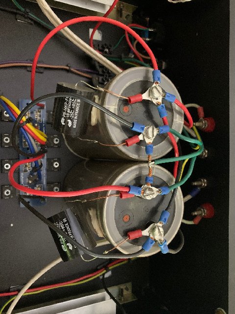
The two 10uF Solens was a test run and I subsequently removed them as the change was very subtle on the high frequencies and I preferred it without them.
The two 10uF Solens was a test run and I subsequently removed them as the change was very subtle on the high frequencies and I preferred it without them.
Last edited:
- recommendations and experiences would be most welcome
Pumpkin, Pumpkin, Pumpkin...
I also itched to play around with the PS on my F4 over the holiday period. I removed the usual CCRCC and replaced it with two 100,000 uF big cans. At first I thought the mid-range was lacking but after some 20 hours burn-in it all came to life and the overall sound is more lively and dynamic sounding than before. I am very happy with the mod.
The two 10uF Solens was a test run and I subsequently removed them as the change was very subtle on the high frequencies and I preferred it without them.
What brand/type of capacitors are those big cans? Thanks...
No hurry Zen Mod. I just wanted to know variable resistor idea could work so I could settle on the holes needed in front panel.
I’d appreciate any knowledge on what a typical resistance range is needed to change bias by 100 to 150 mv...
Rob
S* and S** - whatever you fancy - nice switch(es) or relays controlled with switch(es)
include R* - first lower Iq step
add R** - second lower Iq step
you must get values experimentally - per your wish
with relays - you can wire them Normally On , so lowest Iq if relays aren't energized ........ or the other way
I'm not commenting do you need entire thingie or not , even if I'm using my Papa's Koan almost every day in my workshop , rarely going above 500mW
Attachments
- Home
- Amplifiers
- Pass Labs
- F4 power amplifier