OK.
Monitor pin 2 of the driver board with the scope set to 5v/div.
When remote is applied, does it immediately go high, then drop to 0v after a few seconds?
When remote is removed, does it immediately go high again for a short time?
Monitor pin 2 of the driver board with the scope set to 5v/div.
When remote is applied, does it immediately go high, then drop to 0v after a few seconds?
When remote is removed, does it immediately go high again for a short time?
When powering up it bumps high for about 200milli seconds, then it stays at -3v
When the amp is turned off it slightly bumps up to -2.5v but then sinks to - rail voltage.
Good driver board does the same.
When the amp is turned off it slightly bumps up to -2.5v but then sinks to - rail voltage.
Good driver board does the same.
Last edited:
I'm sorry, I was referring to the PS driver board.
What's the resistance between the negative speaker terminal and the primary ground?
What's the resistance between the negative speaker terminal and the primary ground?
Does your amp have the 1K resistor (R-GND on the diagram) that ties the primary and secondary grounds together?
Yes, 1K resistor in place.
I think a cap was still charged in post #64.
1k measured now between primary and secondary GND.
I think a cap was still charged in post #64.
1k measured now between primary and secondary GND.
Last edited:
When you were looking for the circuit in post 53 (taken from the AQ20 diagram posted previously), it seems that you may have been looking on the audio driver board. That circuit is on the main board. Are the numbers you posted from the main board?
OK. Can you find the circuit posted on the main board?
If so, are the designations the same as in the posted diagram?
If so, are the designations the same as in the posted diagram?
Yes. I didn't fully checked the transistors pin numbers, but with beep mode this seemed excactly the same. Diodes and resistors all correct in place.
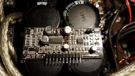
One difference, 1302 on the photo is a 1303 (placed near the driver board)
And is connected to SD pin2 as shown on the photo.
One difference, 1302 on the photo is a 1303 (placed near the driver board)
And is connected to SD pin2 as shown on the photo.
Last edited:
Do you have an LED? Any LED will work.
If so, remove D52.
The LED and a series 1k current limiting resistor will connect between the collector of Q52 and the 12v regulator output of the 12v regulator that powers the 21844s.
Does the LED light for a couple of seconds on startup and momentarily when the amp powers down?
If so, remove D52.
The LED and a series 1k current limiting resistor will connect between the collector of Q52 and the 12v regulator output of the 12v regulator that powers the 21844s.
Does the LED light for a couple of seconds on startup and momentarily when the amp powers down?
The LED gives a veeery tiny blink on startup.
During operation the LED is off.
It lights up when the amp powers off, after 1sec the led goes off smoothly, like a supply cap discharging.
During operation the LED is off.
It lights up when the amp powers off, after 1sec the led goes off smoothly, like a supply cap discharging.
Last edited:
Is it still destroying the FETs if you let it power down, normally with the bad board?
If so, do you have an incandescent lamp that you can insert in series with the FETs to help protect them.
Did the bad board empty the rail caps on low-voltage rails?
If so, do you have an incandescent lamp that you can insert in series with the FETs to help protect them.
Did the bad board empty the rail caps on low-voltage rails?
I assume if I remove the 15v rail to standard rails the output fets still die, yes. There has nothing changed on the driver board yet, and it blew twice with the bad driver board.
The fets already blow up with startup with standard rail voltage.
The board emptied the rail caps with the bad driver board.
With good driver board the caps were still charged.
2 problems with the bad driver board:
It blows while startup (PWM is not delayed until full rail is reached)
It empties rail caps while powering off
Last edited:
If we could find a solution, I'd like it to be as simple as possible. It could be as simple as increasing the 12v (for the driver ICs) input and output cap values. Does this amp have buffer transistors between the driver ICs and the outputs?
The 12v supply generally has 100uf caps on the input and output of the 12v regulator (referenced o the negative rail). I'd try increasing them to 1000uf (if that type of circuit is what you have).
There is likely a way to do something with mute/delay circuit using a jfet but that would require a few more components to make it work. The increase in capacitance would be much easier.
There is likely a way to do something with mute/delay circuit using a jfet but that would require a few more components to make it work. The increase in capacitance would be much easier.
I fitted 1000uf caps in the input and output of the voltage regulators, 4 in total.
This does not have great effect on the output fet switching delay.
It waits about 100ms longer, but not until full rail voltage is reached.
Also the rail voltage is still dumped while powering off.
This does not have great effect on the output fet switching delay.
It waits about 100ms longer, but not until full rail voltage is reached.
Also the rail voltage is still dumped while powering off.
- Home
- General Interest
- Car Audio
- Exploding output fets SPL Dynamics D8s