36k seems extremely low. What are you using to measure the frequency?
Pull Q10 off of the bad board and check it for leakage and open junctions as well as shorts.
Pull Q10 off of the bad board and check it for leakage and open junctions as well as shorts.
If one driver board is muting, the problem must be between the shutdown pin on the header and the 21844 pin 2.
Are you seeing pin 2 clamped to the negative rail during the time it's supposed to be muted/shutdown during the initial mute delay?
Are you seeing pin 2 clamped to the negative rail during the time it's supposed to be muted/shutdown during the initial mute delay?
- rail voltage is excactly -15v.
IX21844N pin2 is on -10v directly, and stays there
Square wave DC voltage on Pin1 is -10.38v
I suppose Pin2 should be -15v at powerup and then slowly sink back to -10v. Once the DC voltage is 'lower' then the -10.38v DC voltage from Pin1 it should start oscillating?
I traced back Pin2 IX21844N several directions. But it seems to be connected to the little green inductors outside of the board, which then connects to another banks IX21844n Pin2.
Last edited:
Negative 10v isn't low enough. That's 5v for pin 2 with reference to the negative rail. Use the negative rail as the reference point for the meter for future voltage measurements.
With the low rail voltage, you can use more robust FETs like the IRFP064 for testing.
Are the inductors in series with pin 2 of all of the 21844s reading low resistance? Compare to the other board for a reference resistance.
With the low rail voltage, you can use more robust FETs like the IRFP064 for testing.
Are the inductors in series with pin 2 of all of the 21844s reading low resistance? Compare to the other board for a reference resistance.
One green inductor fell apart while trying to desolder.
Do you know the value's from these inductors?
Do you know the value's from these inductors?
It's not necessary to remove them to check the resistance.
I don't have the value, definitively. It's not critical but I have 1 diagram that shows 1uH, another that shows 2uH and a 3rd shows 15uH. These are from boards with two 21844s. Maybe someone will have a definitive value from a board like yours.
I don't have the value, definitively. It's not critical but I have 1 diagram that shows 1uH, another that shows 2uH and a 3rd shows 15uH. These are from boards with two 21844s. Maybe someone will have a definitive value from a board like yours.
Both outer inductors rode +-5ohm
Both inner inductors rode +-1.2ohm
Since the colour code is the same on all 4 I tried to measure it out of the board to make sure there was no parallel component which had influence on the measurement. It seems like both outer inductors had a wrong value then.
Is it also possible to test just with +-1ohm resistors soldered in place? Or is it very critical that those components need to be inductors?
Last edited:
The inductors are likely there to prevent noise from causing problems. For testing, the resistors will be OK.
Reading the values on the other board (not removing them), what do you read?
I think the ICs all have independent circuits beyond the inductors. It's odd that they read the same wrong value.
Reading the values on the other board (not removing them), what do you read?
I think the ICs all have independent circuits beyond the inductors. It's odd that they read the same wrong value.
I did repaired this amp before in 2019, i found the invoice with the parts i exchanged. Look for the diode 1ESJ and 4,7uF on the driverboard. I wrote down in my notes CL4 and D3 (XH3)
Last edited:
Thanks for the list Bertje 🙂
Seems like this could be right.
Perry, looks like the driver board has influence on these inductors readings. Removing the driver board makes the other inductors to read the same, about 5ohms.
After measuring, looks like the broken inductor has nothing to do with Pin2 IX21844n. Those inductors are intact, and does indeed have noise on them on one side, which is at output fet switching frequency.
There is a 5ohm resistor in place now and all inductors are noise free and solid.
To answer your previous question. All 4 inductors in serie with IX21844 Pin2 read ok.
Last edited:
Is the driver board in a pluggable header or do you have to solder/desolder?
Here:
"looks like the driver board has influence on these inductors readings. Removing the driver board makes the other inductors to read the same, about 5ohms."
Did you mean that the main board influences the readings?
Here:
"looks like the driver board has influence on these inductors readings. Removing the driver board makes the other inductors to read the same, about 5ohms."
Did you mean that the main board influences the readings?
Correct, it's on good quality headers.
To be more specific with the inductors. There are 6 inductors in front of the driver board. 4 out of 6 inductors are connected to 21844 Pin2, those inductors are OK. When the driver board is installed they read +-1.8ohm each. Without driver board installed they read 5ohm each. Same readings with the good driver board installed.
The other 2 inductors are always 5ohm and seems to be the VSS from the IRS21844s (one from the inductors broke apart).
The inductors I wanted you to check are on the driver board near pin 2 of the 21844s. I thought that one of those was the one that broke. Is that wrong?
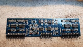
When I posted the value for inductors, these were the ones I was referring to. The green ones on the main board are marked for value.
If you have two boards, do they read the same across the collector and emitter of Q10?
If you have two boards, do they read the same across the collector and emitter of Q10?
Good driver board reads 258K ohm
Bad driver board reads 3M ohm
Between collector and emitter Q10
Bad driver board reads 3M ohm
Between collector and emitter Q10
What's the resistance between pin 2 and pin 3 of the 21844s on each board?
All on each board should read the same so I only need 2 values.
All on each board should read the same so I only need 2 values.
- Home
- General Interest
- Car Audio
- Exploding output fets SPL Dynamics D8s