Lift Q10 on each board and re-measure.
If the readings are the same, you need to break the connection between leg 2 of the 21844 and the board. Lift the terminal and measure the resistance between each terminal 2 (lifted) and terminal 3.
If the readings are the same, you need to break the connection between leg 2 of the 21844 and the board. Lift the terminal and measure the resistance between each terminal 2 (lifted) and terminal 3.
With Q10 lifted, between IRS21844 Pin2 and Pin3:
Bad board, OverLoad
Good board 278K ohm
Pin2 IRS21844 lifted, between Pin2 and Pin3
Bad board, varies from 0.9M to 1.2M
Good board, 1.1M ohm
Keep in mind, good board has IRS21844s
Bad board has IX21844n
Bad board, OverLoad
Good board 278K ohm
Pin2 IRS21844 lifted, between Pin2 and Pin3
Bad board, varies from 0.9M to 1.2M
Good board, 1.1M ohm
Keep in mind, good board has IRS21844s
Bad board has IX21844n
Measured with a different multimeter:
Q10 removed and Pin2 lifted, between Pin2 and Pin3
Good driver board (2Mohm selected on multimeter): 1.15M ohm
Bad driver board (2Mohm selected): nothing visible
Bad driver board (200Mohm selected): 0.00
Multimeter from post #43 now reads:
Good driver board: 1.15Mohm
Bad driver board: OverLoad
Q10 removed and Pin2 lifted, between Pin2 and Pin3
Good driver board (2Mohm selected on multimeter): 1.15M ohm
Bad driver board (2Mohm selected): nothing visible
Bad driver board (200Mohm selected): 0.00
Multimeter from post #43 now reads:
Good driver board: 1.15Mohm
Bad driver board: OverLoad
Last edited:
The ICs may use a different pull-up method.
You could try to increase the initial mute delay time.
Refresh my memory. Did the IRS board have the initial mute delay that allowed the rail to build fully where the IX board starts immediately/earlier?
You could try to increase the initial mute delay time.
Refresh my memory. Did the IRS board have the initial mute delay that allowed the rail to build fully where the IX board starts immediately/earlier?
Correct 🙂
Good board waits until full rail is reached (IRS21844S)
Bad board starts immediately (IX21844N)
Good board waits until full rail is reached (IRS21844S)
Bad board starts immediately (IX21844N)
Last edited:
If you prevent the mute delay cap from charging, does that prevent the bad board from oscillating?
I'm sorry, I don't know which caps influences the muting delay 😕
Is it C1, C5, C7 or C9? I suspect all 4 banks are parallel muted from one supply?
Is it C1, C5, C7 or C9? I suspect all 4 banks are parallel muted from one supply?
First, confirm that the output stage won't start oscillating if you connect the collector to the emitter on Q10 on the driver board.
Drive a signal into the amp to make sure that it has a reason to start oscillating.
Drive a signal into the amp to make sure that it has a reason to start oscillating.
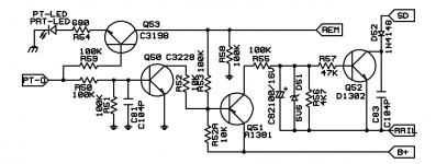
Q53 on the photo seems Q10 (MAX marked)
Q50 on the photo seems Q5 (1D marked, SMBTA42)
Q51 on the photo seems Q4 (2D marked, SMBTA92)
Q52 on the photo is not connected as on the photo.
I can't find a connection between Q52 base and Q51 collector other than a capacitor in series.
Q3 is marked 2A (MMBT3906)
Q50 on the photo seems Q5 (1D marked, SMBTA42)
Q51 on the photo seems Q4 (2D marked, SMBTA92)
Q52 on the photo is not connected as on the photo.
I can't find a connection between Q52 base and Q51 collector other than a capacitor in series.
Q3 is marked 2A (MMBT3906)
Last edited:
The protect light comes on directly after startup, it blinks for about 0.3sec.
Then the green light goes on. The good driver board does the same.
One thing I noticed on the bad driver board. This might be an important thing as well. When turning off the amplifier, the good driver board still keeps it rail voltage in the caps.
When the bad driver board turns off, there is only 2v rail voltage left. It dumps it's rail voltage while powering off.
I have tried several times and spent some time to get it working, but it has not worked yet.
On my old analog philips scope it worked pretty good.
The scope should not be the problem. It should be a pretty good digital scope.
I tried the math function. Ch1 - Ch2 and reversed.
Inverted the channels.
No luck yet....
On my old analog philips scope it worked pretty good.
The scope should not be the problem. It should be a pretty good digital scope.
I tried the math function. Ch1 - Ch2 and reversed.
Inverted the channels.
No luck yet....
- Home
- General Interest
- Car Audio
- Exploding output fets SPL Dynamics D8s