Connect a 10v Zener between the source (anode) and the gate (striped end),
Do you have any fast recovery diodes? Something like a 1n4148 may work.
How fast do the input and output voltages for the 7812 regulator for the 21844s drop, in relation to the remote being removed. Check this in differential mode with probe 2 on the negative rail.
Do you have any fast recovery diodes? Something like a 1n4148 may work.
How fast do the input and output voltages for the 7812 regulator for the 21844s drop, in relation to the remote being removed. Check this in differential mode with probe 2 on the negative rail.
Yes, I have a 1N4148 diode
With the 10v zener diode installed there is also no output switching.
The 7815 output drops almost directly after remote is removed.
Hard to check very precise since the scope is a bit delayed in showing results.
With the 10v zener diode installed there is also no output switching.
The 7815 output drops almost directly after remote is removed.
Hard to check very precise since the scope is a bit delayed in showing results.
Connect the gate/Zener to the 12v output of the 7812 through a 10k resistor.
Does the amp oscillate?
Does it drain the rail caps?
Does the amp oscillate?
Does it drain the rail caps?
The amp oscillates, it drains the rail caps during power off.
Amp oscillates directly after starting up
Amp oscillates directly after starting up
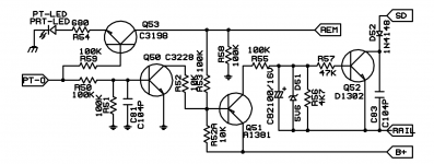
Connect the anode of a 1N4148 to the anode of D22. Connect the cathode of the 1N4148 to the gate of the jfet, via the 10k resistor after removing it from the output of the 7812.
Does that prevent the rail caps from being drained?
Does that prevent the rail caps from being drained?
The jfet needs to have positive voltage (relative to its source) to be switched off. 0v to switch on. The 12v regulator voltage wasn't dropping quickly enough.
The jfet has a limited voltage that it can withstand at its gate. The Zener is there to protect it. It will always remain connected across the jfet gate and source.
The 1N4148 is going to supply voltage from the transformer to the gate of the jfet via the resistor. This voltage will drop much quicker because there is no capacitor when the PS switches off
It's D22 on the AQ20 diagram (may be different in your amp). There are 4 diodes (including D22) that are connected to a dedicated winding on the power transformer. The diodes are sometimes near the transformer and sometimes near the 7812.
Thanks for the explaination 🙂
This make the working of Jfet more clear.
You were right, D22 (4 diodes) were hidden near the transformers under a load of transformer windings.
Currently, the output does not switch. There is no potential difference between D22 anode and Jfet Source
This make the working of Jfet more clear.
You were right, D22 (4 diodes) were hidden near the transformers under a load of transformer windings.
Currently, the output does not switch. There is no potential difference between D22 anode and Jfet Source
0.15 volt between Gate and Source
0 volt between D22 anode and Source
I connected the 10k resistor and 1n4148 to D23 cathode, now it oscillates.
It barely dumps rail voltage now anymore.
The only dump is 14v rail voltage idle, to 13.22v after powering off
0 volt between D22 anode and Source
I connected the 10k resistor and 1n4148 to D23 cathode, now it oscillates.
It barely dumps rail voltage now anymore.
The only dump is 14v rail voltage idle, to 13.22v after powering off
Last edited:
This is likely not going to be a viable solution due to requiring a bit too complex but it may lead to a better solution.
0.15v may be a meter error.
Try paralleling a very small capacitor (0.001uF) across the Zener. Does that prevent any rail dumping?
Are you sure that the rails didn't drop approximately the same when the driver ICs were disabled?
0.15v may be a meter error.
Try paralleling a very small capacitor (0.001uF) across the Zener. Does that prevent any rail dumping?
Are you sure that the rails didn't drop approximately the same when the driver ICs were disabled?
Yes, it really does dump slightly. On the scope there is a tiny drop visible.
When the drivers are disabled there is no slight bump. It sinks smoothly then.
With a small cap across the zener (100pf) it still dumps slightly.
From 13.75v to 13.25v
When the drivers are disabled there is no slight bump. It sinks smoothly then.
With a small cap across the zener (100pf) it still dumps slightly.
From 13.75v to 13.25v
Well, that's better than the 0.15v you previously read. With 10v, that ensures that the jfet is completely off. A good thing.
Do you have any mismatched (no use for the final repair) output FETs to test on full rail voltage to see if the rails get drained as they were without the jfet?
Do you have any mismatched (no use for the final repair) output FETs to test on full rail voltage to see if the rails get drained as they were without the jfet?
Yes 🙂
About the output fets, it probably still blows the fets.
The fets blew up twice with powerup on full rail voltage.
The output fets directly starts oscillating as soon as the remote is applied.
It does not wait until full rail voltage is reached.
About the output fets, it probably still blows the fets.
The fets blew up twice with powerup on full rail voltage.
The output fets directly starts oscillating as soon as the remote is applied.
It does not wait until full rail voltage is reached.
- Home
- General Interest
- Car Audio
- Exploding output fets SPL Dynamics D8s