With pleasure vargas! 🙂 But unfortunately I cant do it until tuesday...got some things to do tomorrow. But dont expect to much, because I'am actualy searching for a good case. I was considering if I could use a defect Yamaha Amp or anything like this. Than I would make a new frontplate and all would be fine. Or does someone have antoher good idea?
Cheers,
Buckitronic
I just found this website that have many size chassis maybe you will like it
🙂 Modushop by Hi-Fi 2000
Attachments
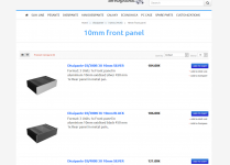
Thanks Vargas, but I already knew this website. Its just a bit expensive for a student if you know what I mean. :/ ( with the shipping costs ) But such a Peasante would be a very nice piece of chassis. And do you maybe know a website for power switches like those in yamaha amplifiers? I never saw such a switch/button available. :/
Did you also built a TO3 /SymAsym ? Do you have pictures of your build? 🙂
Cheers,
Buckitronic
Did you also built a TO3 /SymAsym ? Do you have pictures of your build? 🙂
Cheers,
Buckitronic
An externally hosted image should be here but it was not working when we last tested it.
An externally hosted image should be here but it was not working when we last tested it.
Hi Andrew,
Tone it down Andrew. You are probably annoyed with something else as well and decided to blow off steam. But this isn't fair to our members and certainly doesn't help Buckitronic, or anyone else.
-Chris
Sorry, no. Probably most other people as well.Did anybody read Buck's posts last night?
Not helpful. Certainly the more confident members would have - obviously!Why did you not jump in and tell him/her that they do NOT need to unsolder components to be able to measure a VOLTAGE?
I am appalled that you would give an impression that this membership doesn't care, because you are well aware that we do care.I am appalled that the Membership left you hanging out there proposing to unsolder components to try to measure current.
Tone it down Andrew. You are probably annoyed with something else as well and decided to blow off steam. But this isn't fair to our members and certainly doesn't help Buckitronic, or anyone else.
-Chris
With pleasure vargas! 🙂 But unfortunately I cant do it until tuesday...got some things to do tomorrow. But dont expect to much, because I'am actualy searching for a good case. I was considering if I could use a defect Yamaha Amp or anything like this. Than I would make a new frontplate and all would be fine. Or does someone have antoher good idea?
Cheers,
Buckitronic
Recycling is a good idea, the spirit is in the creativity
 😉
😉Thanks Vargas, but I already knew this website. Its just a bit expensive for a student if you know what I mean. :/ ( with the shipping costs ) But such a Peasante would be a very nice piece of chassis. And do you maybe know a website for power switches like those in yamaha amplifiers? I never saw such a switch/button available. :/
Did you also built a TO3 /SymAsym ? Do you have pictures of your build? 🙂
Cheers,
Buckitronic
An externally hosted image should be here but it was not working when we last tested it.
An externally hosted image should be here but it was not working when we last tested it.
Hello sir I haven't but I do have plans to order a few mister Rudi's design I have a clone PCB but "only for personal use" I already simulated and responds really well bias adjustment and all that good to go 🙂
Regards
Juan
Attachments
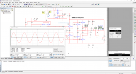

@vargas Nice! Totaly support your idea of building one! You wont regret it! I've also fired up my stereo build ( the first tries were mono) and it sounds realy great! Now I just have to find a cheap good looking amp chassis. 🙂 Also have someone for the front panel...asked my electronic professor if I could use the universities own CNC machine and he just said yes! 🙂 But I have one question, how is your "anaylsis programm" called? At the university we have PSpice 9.1, but unfortunately its not Windows 10 compatible... :/ Btw. looks like some good results!
@abetir Thanks! 🙂 I have the thought to use a black Chassis and to add 2 dark wood panels on both sides. (oiled or somehting with a little shiny look) Could look nice, but I'm open for other szggestions.
Cheers,
Buckitronic
@abetir Thanks! 🙂 I have the thought to use a black Chassis and to add 2 dark wood panels on both sides. (oiled or somehting with a little shiny look) Could look nice, but I'm open for other szggestions.
Cheers,
Buckitronic
I use multisim 14 a free version from Mouser or sometimes I use LTSpice, but LTSpice is a bit more configurable than multisim 14 , I only do simple simulation to see how many watts and to see the bias adjustment and frequencies respond but no too do really more complicated task circuit analysis 🙂 I leave that to the experts jejejejeje
Regards
Juan
Regards
Juan
Emitter Base Blockers
Hey Guys,
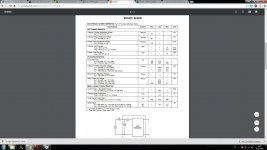
I have a question about the Resistors R22,35,24,80
R14 , R40 and R42 because in the reichelt Chart there are only 4 Resistors 1.2Ohms 1W instead of 8 in the silkscreen of the Black Beauty PCB. Which Resistors do I need for these 7 Resistors ?
Hey Guys,
I have a question about the Resistors R22,35,24,80
R14 , R40 and R42 because in the reichelt Chart there are only 4 Resistors 1.2Ohms 1W instead of 8 in the silkscreen of the Black Beauty PCB. Which Resistors do I need for these 7 Resistors ?
Hey Guys,
I have a question about the Resistors R22,35,24,80
R14 , R40 and R42 because in the reichelt Chart there are only 4 Resistors 1.2Ohms 1W instead of 8 in the silkscreen of the Black Beauty PCB. Which Resistors do I need for these 7 Resistors ?
And Can i use for the 0,22 Ohm MPC's normal 0,27Ohm 5W Resistors ?
Which schematic and PCB are you refering in your previous post?
For emitter resistor any good quality, non-inductive should be OK.
For emitter resistor any good quality, non-inductive should be OK.
Which schematic and PCB are you refering in your previous post?
For emitter resistor any good quality, non-inductive should be OK.
Hi and thanks for your answer. I bought the PCB's on diy audioshop and I build it now with the PDF straight from this page. If you need a Link just ask.
Regards
Yeah, all info you could give would be great, not leting me do the search... 🙂
Here is the Link ...
http://anleitung.diy-audio-shop.de/SYMASYM-BB.pdf
And I have an another question. Can I use MJL3281A/1302A instead of the NJW series ? In the PDF is the MJL4XXXX series listed but I heard that the MJL3XXXX is in some points better than the 4-series. I think the Power is in both cases more than enough (200W MJL3XXXX and 230W the MJL4XXXX) 😕
Help 🙁
PS: I use 2x 27V 200VA Transformers if this helps...
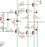
Sorry, still hard to find all resistors with a blurred schematic like this.Hey Guys,
I have a question about the Resistors R22,35,24,80
R14 , R40 and R42 because in the reichelt Chart there are only 4 Resistors 1.2Ohms 1W instead of 8 in the silkscreen of the Black Beauty PCB. Which Resistors do I need for these 7 Resistors ?
And there are more version of the PCB as well in that 40 pages long doc.
So please prepare your question with as much info as possible
with screenshots and the critical sections marked with paint, etc.
It's really time consuming to search for the info with this much of info.
MJL: yes, they should work as well!
But if you change some of the components use the bulb method to check for oscillation, etc.
Attachments
Last edited:
Sorry, still hard to find all resistors with a blurred schematic like this.
And there are more version of the PCB as well in that 40 pages long doc.
So please prepare your question with as much info as possible
with screenshots and the critical sections marked with paint, etc.
It's really time consuming to search for the info with this much of info.
MJL: yes, they should work as well!
But if you change some of the components use the bulb method to check for oscillation, etc.
Alright, thanks. Btw I found the right resistors so the last question is obsolet now. But I have another question can i change this capacitor marked in my screenshots with a 22pF one ?
Attachments
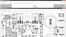
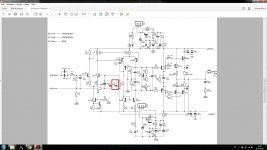
Most amplifiers are very sensitive to small changes in that feedback capacitor.
One well regarded amplifier was OK with 22pF there.
When built with a different output device pair, the amplifier oscillated.
The 22pF had to be reduced <<10pF
Some amplifiers will only tolerate a 4p7F here to maintain adequate stability margins.
You have to check your as built stability margins.
Adding a resistor in series with the capacitor may help, but agian you need to check your stability margins.
Most amplifiers are very sensitive to small changes in that feedback capacitor.
One well regarded amplifier was OK with 22pF there.
When built with a different output device pair, the amplifier oscillated.
The 22pF had to be reduced <<10pF
Some amplifiers will only tolerate a 4p7F here to maintain adequate stability margins.
You have to check your as built stability margins.
Adding a resistor in series with the capacitor may help, but agian you need to check your stability margins.
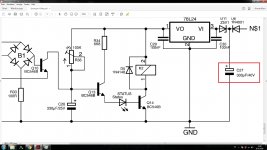
Ok thanks, 10pF then, another question, can I change this Capacitor to 470uF 40V instead of 330uF 40V ?
PS: I have a second question before I forget it... Which function has the Potentiometer R38 with 100Kohm ?
Attachments
Last edited:
Of course. BTW: the attachments are now perfect! 🙂
It's a lot easier and faster to answer to questions prepared like this! 😉
It's a lot easier and faster to answer to questions prepared like this! 😉
Check your as built stability margins. I don't properly understand amplifier DESIGN and cannot tell anyone why that capacitor is so sensitive in the way it affects the outcome. I do know that a reactive load can inject a signal back into the -IN via that capacitor and that may be a clue to why it can dominate stability behaviour.Ok thanks, 10pF
Yes that input capacitor just provides a bit more ripple attenuation before the regulator. But it would do that even better if there was some resistance between the supply and the capacitor. Add in a resistor in series with D6then, another question, can I change this Capacitor to 470uF 40V instead of 330uF 40V ?
VR38 adjusts the time delay.PS: I have a second question before I forget it... Which function has the Potentiometer R38 with 100Kohm ?
C26 charges up via VR.
The time constant is VR*Capacitance.
It reaches ~2/3rds of the 24V supply in one RC time constant.
The timing transistor starts to switch on when C26 charge reaches ~ VbesatQ14+VfLED+VbeQ13
that voltage is ~3.3V. This is only 14% of the supply, so the transistor turns on LONG before the capacitor reaches 16Vdc.
The current through R34 must be sufficient to saturate Q14. I calculate IcQ13 ~3mA.
Will that saturate Q14 for the relay you intend to use?
BTW, the circuit does not need bc546. These are 60Vce0 and the regulator is 24V.
Any 30V to 50V Vce0 will do.
C26 must be reformed slowly before assembly.
Otherwise leakage will ruin the timing which will constantly change over some weeks as the capacitor reforms in circuit.
Personally I would use a fixed value for R38 @ 300k to 1M and use an MKT for the timing capacitor. Much more reliable. 1M0 would require a higher gain transistor for Q13, try hFE >200
Last edited:
Check your as built stability margins. I don't properly understand amplifier DESIGN and cannot tell anyone why that capacitor is so sensitive in the way it affects the outcome. I do know that a reactive load can inject a signal back into the -IN via that capacitor and that may be a clue to why it can dominate stability behaviour.Yes that input capacitor just provides a bit more ripple attenuation before the regulator. But it would do that even better if there was some resistance between the supply and the capacitor. Add in a resistor in series with D6VR38 adjusts the time delay.
C26 charges up via VR.
The time constant is VR*Capacitance.
It reaches ~2/3rds of the 24V supply in one RC time constant.
The timing transistor starts to switch on when C26 charge reaches ~ VbesatQ14+VfLED+VbeQ13
that voltage is ~3.3V. This is only 14% of the supply, so the transistor turns on LONG before the capacitor reaches 16Vdc.
The current through R34 must be sufficient to saturate Q14. I calculate IcQ13 ~3mA.
Will that saturate Q14 for the relay you intend to use?
BTW, the circuit does not need bc546. These are 60Vce0 and the regulator is 24V.
Any 30V to 50V Vce0 will do.
C26 must be reformed slowly before assembly.
Otherwise leakage will ruin the timing which will constantly change over some weeks as the capacitor reforms in circuit.
Personally I would use a fixed value for R38 @ 300k to 1M and use an MKT for the timing capacitor. Much more reliable. 1M0 would require a higher gain transistor for Q13, try hFE >200
Wow!!! thank you for that much information, so step for step,
For the R38: I have a 0,6W 480Kohm Resistor here will this do the job ? And on which two pins must I solder the R. ? between 1 and 3 ? (Sorry to ask but it's my first amp. project
Q14: yes
BC546B : Yeah I see but I have many of these trans. so why not 😀
Q13: Which type should I use ? I have only 546B and 2N5551 here 😕
What about the Input Trans. Q1 and Q2, in the PDF is listed that I can use 550C 2N5551 ... but I only have the BC546B here is it bad to use it for the 550C?
In the Datasheets stands that they have similar properties only the hfe is lesser than the 550C ...
Attachments
- Home
- Amplifiers
- Solid State
- Explendid amplifier designed by Michael Bittner, our MikeB