oops
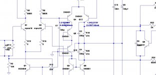
below is the picture after adding Q10
thanks
best regard
below is the picture after adding Q10
thanks
best regard
Attachments
![Symasym 5_3[1]_new.jpg](/community/data/attachments/440/440379-e3f71c59614e48adc55aa10622d2123b.jpg?hash=4_ccWWFOSK)
Last edited:
oops
below is the picture after adding Q10
thanks
best regard
Hi, as Keantoken just mentioned, you have added a diode, made out of transistor, shifting the level 0.7V up on the left side of the diff cascade, making the voltages on the left and on the right more equal with no input signal. Now, see what happens, when there is an input signal - voltage on the right moves up and down, voltage on the left stands still. The fact, that it stands 0.7V higher, does not change anything.
In differential cascade, balance of the currents is much more important. With regards to the voltage difference - Early effect has to be considered, that's why a common-base transistor is already there on the left, serring the voltage of the left diff collector close to the ground level. Plus/minus 0.7V don't make any difference in this situation.
Cheers,
Valery
Hi guys, I have a little problem with my TO3-SymAsym build. I think I've soldered everything in the right order and direction. Actually I'am finishing the second AMP board to controll any differnces between this and my first AMP Board. I checked everything before and after the soldering was done, but there is some fault in my build, because I dont have 0mV about both emitter resistors. The 40W light bulb tester is smouldering a bit brighter as I think it should, but it could be because of the voltage drop != 0mV. I've measured a voltage drop of about 43mV over both emitter resistors, but my potentiometer is full on 480Ω!!! Could it be, that a little spread of my input transistors 2SK170L is causing such an voltage drop? ( Hfe matched, but i think the emitter-collector voltage is not the same? Or is this thought stupid? ) And what should I do then? Because the claimed quiescent current would already be appointed....
(I've measured the voltage drop over the 10Ω 2W(!!!) resistors on the input side ( 10Ω for the first start up, and with those 43mV over the emitter resistors I've measured a voltage drop of about 4,3V which is about 430mA Current on both sides)
I hope someone is reading this and is about to help me. And sorry for my bad english, I'am still learning. 🙂
Cheers,
Buckitronic
Hey Andrew,
if I'am right you mean the BD139 or? There I've measured a voltage drop of about 1,933V ( collector-emitter voltage )! ( With just +-14V VEE and VDD, because the light bulb tester takes about 115V on the primary side for himself ) Its all a bit weird.....
But thanks for the first answer!
Cheers,
Buckitronic
1.933Vbias is fed to the bases of the drivers.
Each driver will drop ~600mVbe
That leaves 1.933-2*(600+600) ~ 0.733V
This is fed to the bases of the output devices.
It splits roughly equally to the upper and lower devices leaving ~366mVbe on each output.
The outputs do not turn on. They pass no current.
Monitoring the output bias current at the outputs shows ZERO.
You learn nothing by monitoring the output. It reads ZERO.
You need to monitor both the Vbias @ the multiplier AND either the driver emitter resistor current, or the output device emitter current. Two or three voltmeters clipped on to those test points allow you to use two hands to carefully make adjustmens and record the results.
Then you will see Vbias changing as you adjust the VR in the multiplier.
To make this test and adjust the output bias, the output should have no load. It does need the Output Thiele Network to help maintain stability.
The input should have a shorting plug fitted.
Last edited:
Helloy Andrew,
again thanks for your helping attempts! But unfortunately I dont have more than one multimeter...I'am a so called "poor student". ^^ So my only chance is to measure the Vbias at the multiplier. For measuring a current I would have to unsolder one 0,22Ohm resistor and than I just could monitor one current! But I also can measure the votlage drop about both output emitter resistors and there my multimeter shows 43mV without adjusting the potentiometer. I realy dont know why this happens. :/ And when im turning the potentiometer more and more to zero the light bulb glows more and more ( whats clear, but it's said that it just should smoulder a bit .... so i fear a to high current flowing, if I adjust it ). Do you have any idea? I've drilled the last holes of AMP board 2 so I can see any differences, but I think there will happen the same.
I also have to say, that I forgot to insulate the srews of the MJE's at the first start up, but I dont think that anything has gone ill! Do you maybe have a value of the Vbe multiplier to achieve?
Cheers,
Buckitronic
Hello,
here I'am again and I dont know what I've done? I wanted to remeasure the voltage drop over the two emitter resistors of the output stage and then all of the sudden there came like a "plop" the flash of the light bulb and then it was off... I thought "Oh no did I've done a big mistake?!" but no, I changed the light bulb and to my surprise all was working as it should? I measured a DC Drop of 0mV on the output stage, but full +-35V at the input and on the 10Ohm resistor a drop of about 700mV! I thought: "lets try it" and removed them after a while. I adjusted the potentiometer and like the manuel said after ~10-20 rounds I've got my Voltage drop of about 35mV over both emitter resistors . I also checked the Voltage of the Vbe multiplier and there I've measured a drop of 2,3V...is this a good value? And now after adjusting the quiescent current the light bulb tester is just smouldering a bit, like it should. I realy realy dont know which mistake I had at the first start up? So if the 2,3V of the Vbe multiplier and the 35mV over both emitter resistors are right...is everything okay or? Andrew can you confirm my thought?
Cheers,
Buckitronic
Did anybody read Buck's posts last night?
Why did you not jump in and tell him/her that they do NOT need to unsolder components to be able to measure a VOLTAGE?
Why did you not jump in and tell him/her that they do NOT need to unsolder components to be able to measure a VOLTAGE?
I'am reading a bit sarcasm or? 😉 Sorry for not thinking about my doing...Ohms law ... I was a bit "confused" about measuring the current. But know everything seems okay. The bulb tester is just smouldering a bit and I've got a voltage drop of 34mV over both emitter resistors which means a current flowing of 77mA. So as I'm not mistaken, everything is fine or? And thanks for your help Andrew!
Cheers,
Buckitronic
Cheers,
Buckitronic
Hi!
Not so sure with your definition of light bulb "smouldering" , my experience is that, the light bulb should go off on a stable system. On some system the light bulb flashes momentarily at power on. I do think this has to do with the power supply implementation. (e.g. massive capacitance).
Now if at power on your light bulb flashes or dims momentarily then goes off, I do think the circuit is fine, but if it dims all the way while the circuit is plugged (energised). A fault still exists in the circuit. However when you try to play music in it while still the light bulb is attached it may light up as the circuit pulls more current.
I do think others has this method of using a low wattage bulb first because a high wattage bulb cannot detect a little current fault.
(Correct me If I'm wrong)
Back to topic, I'm not so sure how many pairs is the TO-3 version but 77ma may look a bit over. Have you tried around 24mv across both emitters? If you have a robust output devices and a large heatsink then 77ma should be fine. Try to inject some music and see how the sonic goes. I personally made a pcb design of SYMASYM to fift my preferred components, unfortunately time is not cooperating..
As I am no expert, I hope I have helped in a small way.
Cheers!
Depending on bias setting a 40W light bulb will burn dimly if the bias is high enough. Once you see that everything is OK you need to disconnect the light bulb and plug in directly to set the final bias on the amp. The light bulb will limit the current to the amp so without it your bias will likely be a bit higher.
Blessings, Terry
Blessings, Terry
Hello,
here I'am again and I dont know what I've done? I wanted to remeasure the voltage drop over the two emitter resistors of the output stage and then all of the sudden there came like a "plop" the flash of the light bulb and then it was off... I thought "Oh no did I've done a big mistake?!" but no, I changed the light bulb and to my surprise all was working as it should? I measured a DC Drop of 0mV on the output stage, but full +-35V at the input and on the 10Ohm resistor a drop of about 700mV! I thought: "lets try it" and removed them after a while. I adjusted the potentiometer and like the manuel said after ~10-20 rounds I've got my Voltage drop of about 35mV over both emitter resistors . I also checked the Voltage of the Vbe multiplier and there I've measured a drop of 2,3V...is this a good value? And now after adjusting the quiescent current the light bulb tester is just smouldering a bit, like it should. I realy realy dont know which mistake I had at the first start up? So if the 2,3V of the Vbe multiplier and the 35mV over both emitter resistors are right...is everything okay or? Andrew can you confirm my thought?
Cheers,
Buckitronic
Did anybody read Buck's posts last night?
Why did you not jump in and tell him/her that they do NOT need to unsolder components to be able to measure a VOLTAGE?
No sarcasm.I'am reading a bit sarcasm or? 😉 Sorry for not thinking about my doing...Ohms law ... I was a bit "confused" about measuring the current. But know everything seems okay. The bulb tester is just smouldering a bit and I've got a voltage drop of 34mV over both emitter resistors which means a current flowing of 77mA. So as I'm not mistaken, everything is fine or? And thanks for your help Andrew!
Cheers,
Buckitronic
I am appalled that the Membership left you hanging out there proposing to unsolder components to try to measure current.
The alternative method of measuring voltage drop across a known resistor is much preferred to unsoldering a good assembly.
It is my view that I and most others can ignore the ammeter function on our instruments.
It is extremely rare that we need to interrupt a circuit to insert an ammeter to measure current. If one can find the current some other non invasive way then look for that solution.
There is one situation where one could do this. At the fuse holder in the secondary DC supply. One can insert an ammeter after removing the fuse. But even here it is better to insert a dummy fuse with the fuse wire replaced with a low value resistor. I have 1r0 and 10r resistors soldered into dead fuses for just such a current measuring role.
500mAdc through a 1r0 resistor in the fuseholder will read 500mVdc on the 2.000Vdc scale of the voltmeter and usually do it to a better accuracy (±0.2% of reading +1digit and ±resistor tolerance) than the bult in ammeter (±0.5%+3digits). Check your volts and amps tolerances.
Last edited:
Hi!
Not so sure with your definition of light bulb "smouldering" , my experience is that, the light bulb should go off on a stable system. On some system the light bulb flashes momentarily at power on. I do think this has to do with the power supply implementation. (e.g. massive capacitance).
Now if at power on your light bulb flashes or dims momentarily then goes off, I do think the circuit is fine, but if it dims all the way while the circuit is plugged (energised). A fault still exists in the circuit. However when you try to play music in it while still the light bulb is attached it may light up as the circuit pulls more current.
I do think others has this method of using a low wattage bulb first because a high wattage bulb cannot detect a little current fault.
(Correct me If I'm wrong)..................
the Mains Bulb Tester is a very good, no damage, way of checking the wiring of a new, or modified project.Depending on bias setting a 40W light bulb will burn dimly if the bias is high enough. Once you see that everything is OK you need to disconnect the light bulb and plug in directly to set the final bias on the amp. The light bulb will limit the current to the amp so without it your bias will likely be a bit higher. ...............
But do not try to set up bias voltages/currents with the bulb in circuit.
The Bulb filament resistance very effectively increases the source impedance of the mains supply.
the voltage applied to the mains transformer and the voltage out of the secondary will be all over the place if one tries to draw significant and/or variable current into the load.
In the worst case a 240Vac supply could momentarily apply just 5Vac to the transformer.
@abetir Yes I've got a big monster of heatsink! 😉 So all will be fine and if not there is at every time the chance of lowering the bias.
@still4given Yes I'am using a 40W light bulb, so there is just the wire inside the glass body smouldering a little bit! I will try to adjust the bias without the light bulb. I hope all will be fine.... And there are 2 Canton GLE's overe here waiting since 2 weeks to pleasure my ears. 🙂
@AndrewT Yes I also catched this... with the light bulb smouldering a bit there is just a voltage drop of +-30V on the PSU. And thanks for this clue, sometimes I used the ammeter when the 10Ohm resistors were inserted, but thats the easier way ( measuring the voltage drop and calculate the current ).
Big thanks to all of you! Nice that there is other folk around to help me! 🙂
Cheers,
Buckitronic
Good to hear that,🙂 If you are not having DC issues at the output then load it up, use a dummy speaker first. I personally test my build after assembly using dummy load for about 6hrs playback time. Nice speakers you have in there. 😉
Cheers!
Cheers!
Big thanks to all of you guys! Both channels are working fine and as they should! 🙂 I'am so happy right now!!! And to my pleasure no one lied about the TO3-SymAsym, it sounds soooo good! After playing ~15min you're getting goose pickels with the TO3 and this nice pair of Canton GLE! More than 30 years old but the sound is just a dream! Again big thanks to you guys! At least I'm not to stupid for soldering. ^^
Cheers,
Buckitronic
Cheers,
Buckitronic
Big thanks to all of you guys! Both channels are working fine and as they should! 🙂 I'am so happy right now!!! And to my pleasure no one lied about the TO3-SymAsym, it sounds soooo good! After playing ~15min you're getting goose pickels with the TO3 and this nice pair of Canton GLE! More than 30 years old but the sound is just a dream! Again big thanks to you guys! At least I'm not to stupid for soldering. ^^
Cheers,
Buckitronic
please sir post some pictures 🙂 of your build
Regards
Juan
With pleasure vargas! 🙂 But unfortunately I cant do it until tuesday...got some things to do tomorrow. But dont expect to much, because I'am actualy searching for a good case. I was considering if I could use a defect Yamaha Amp or anything like this. Than I would make a new frontplate and all would be fine. Or does someone have antoher good idea?
Cheers,
Buckitronic
Cheers,
Buckitronic
- Home
- Amplifiers
- Solid State
- Explendid amplifier designed by Michael Bittner, our MikeB