I still listen to my Symasym from time to time. Michael got it right.
You probably need a scope to see oscillation but since your bias is staying steady you are probably OK. Oscillation will generally cause heating problems and you will often hear some hash or hissing. Maybe someone else will have another way to check for oscillation when not using a scope.
You probably need a scope to see oscillation but since your bias is staying steady you are probably OK. Oscillation will generally cause heating problems and you will often hear some hash or hissing. Maybe someone else will have another way to check for oscillation when not using a scope.
Hi!..sorry missed this one,
True, lay-out was very critical according to the designer, I remember the original (first) lay-out was revised because of grounding issues..and nope I have not built my lay-out up to this date. A revision was made again (attached) this one has symmetrical approach, I am actually a fan of Elektor design lay-out.
I'd love to and I always do add 2 signal diodes on the ground lift resistor but in the Symasym I strictly followed the original schematic..unless there is a reason to do so. 😉
I guess the legs (pin) spacing should be fine when mounted vertically the MJE's figure in the lay-out was not the actual length of the pins, the TO-220 figure is for representation only.
Never thought that the actual resistor was 0.5w, I was not subscribing to the thread (long time ago 🙂) I've been browsing Michael's and Pavel's SymAsym site. Thank you for the clarification.
The double back to back input elytics was there as an option, it could actually be a single non-polar elytic or an MKP polycaps whichever fits, more actually as a preference by the builder. Nothing to do with Carlos Blame ST 🙂
The problem is, I don't have much experiences with input fets as I mentioned above I stick to the first SymAsym done by Michael.
Regards!
Very neat but quite a radical departure from Michael's layout. I note that Michael said at the outset that layout was critical so interested to know if you've built and measured performance yet?
True, lay-out was very critical according to the designer, I remember the original (first) lay-out was revised because of grounding issues..and nope I have not built my lay-out up to this date. A revision was made again (attached) this one has symmetrical approach, I am actually a fan of Elektor design lay-out.
A couple of observations in the meantime: as you're paying attention to Pavel's suggestions did you not want to put parallel reversed diodes around R2?
I'd love to and I always do add 2 signal diodes on the ground lift resistor but in the Symasym I strictly followed the original schematic..unless there is a reason to do so. 😉
Are your MJE15030/1's too far away from their pads? Their legs aren't very long. So if you're mounting, for instance, on 3mm angle aluminium you need to allow for this, plus the board thickness plus half the thickness of the transistor itself in order to have enough of the leg poking thru to solder.
I guess the legs (pin) spacing should be fine when mounted vertically the MJE's figure in the lay-out was not the actual length of the pins, the TO-220 figure is for representation only.
R1 and R3 don't need to be more than 0.5w according to post 3142. I've sourced Welwyn 1 watt MPF1's for these which at 6.3mm long are much smaller than you have. You could lose several mm on each side of your board. Even the 2w MPF2's are only 10mm.
Never thought that the actual resistor was 0.5w, I was not subscribing to the thread (long time ago 🙂) I've been browsing Michael's and Pavel's SymAsym site. Thank you for the clarification.
Is there a compelling reason for making a bipolar cap out of 2 electrolytics at C1? I know the WIMAs are impossible to get at 4.7uF outside of Germany but why not use a single reversed electrolytic as Micheal suggests at post 2279 and 2438. Or are we doing this just because that's what Carlos did with Blame?
The double back to back input elytics was there as an option, it could actually be a single non-polar elytic or an MKP polycaps whichever fits, more actually as a preference by the builder. Nothing to do with Carlos Blame ST 🙂
Did you not want to use 2SK170 at Q1/2?
The problem is, I don't have much experiences with input fets as I mentioned above I stick to the first SymAsym done by Michael.
Regards!
Attachments
R1 & R3 are 1r2
If they have a 500mW rating, then they have a maximum continuous current rating of ~645mAdc.
For 50% duty factor this would allow 1290mApk.
1.29A of base current is plenty for normal peak transient output of the output devices.
Would the gain of an output device have fallen 8 when Ic is 10Apk?
That 10Apk would then require 1.25Apk of base drive.
500mW is OK.
BUT,
during abuse this base current can be exceeded.
It's another component that needs to be checked after you have an incident, or have blown a fuse.
I have twice had a base stopper blow. Better that than burning out the output device.
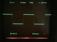
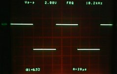
Hi, given thanks for reply, appreciate. i have a scope but don't know what to look for, tested with sine wave from 20 to 20kHz it seen nice and clean sine wave at the output and test with 1khz square wave is same clean no rigging or over shoot ( don't have signal gen the square wave source from the scope cal 1Vp-p, and test it with low volume... is late, middle of the nigh ) ... did i miss some thing? please take a look the picture i take.
BTW i have change the sysm transistor .... input Q1/2- 2n5551, T1- C3421, driver A1837/C4793, output C5198/A1941 and C14-10pf compare to the sysm befor, i more like it the old sysm, this new transistor sound more wide and the old more solid. maye be will change it back tomorrow ( don't know the news transistor is fake or ...). any suggestions should i change the C19-470uf (ELNA Cap)...
would you mind let me know your sysm setting up and do you matching the driver and output transistor? thanks.
BEST REGARD
Attachments
Omg .... after more then a month checking, is not the symasym problem. is the 50K volume over kill..... after changing the volume control to 25k, symasym work good. bass and detail is deep and clear.
after changing the volume control to 25k, symasym work good. bass and detail is deep and clear.It is good you didn't gave up..! (That's why I use 10k pots wherever possible...)
And its a good example when just a little component can ruin a whole system.
Interesting to imagine when somebody reports his own experiences based on a similar/improper setup... 🙂
BTW: I just played around with an own symasym implementation: 60V, EF3, 2P OPS, different Iq, faster Qs, HF comp, DC servo, compact PCB, etc...
And maybe could someone (who has the original version and a scope) try a test with 100kHz square wave load/unloaded?
Mine has great response till several 100kHz and I am just curious to the basic versions performance. Thx!
Hi Cortez, you r right improper setup can ruin a whole system.
ok for the moment i'm busy searching for a good tone control circuit.
btw wow, 100kHz square wave load/unloaded is extreme!
anyway do you have a good 100khz square wave generator circuit?
thanks best regard
ok for the moment i'm busy searching for a good tone control circuit.
btw wow, 100kHz square wave load/unloaded is extreme!
anyway do you have a good 100khz square wave generator circuit?
thanks best regard
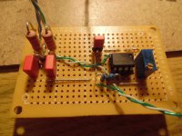
I have a 1MHz function generator, but before that I made a simple sq. generator with a very fast opamp used in "comparator mode".
As I remember it was very good as a source. I'll take it out from my drawer to check it for you.
As I remember it was very good as a source. I'll take it out from my drawer to check it for you.
I found it..! 🙂
It's something like this:
Square wave generator using uA741
I built it for 1kHz, I dont know wether its ideal for 100kHz range.
It's something like this:
Square wave generator using uA741
I built it for 1kHz, I dont know wether its ideal for 100kHz range.
Attachments
Hi, thanks nice tiny gadget and i found this Squarewave Testing
it seem more promising for high frequency and slew rate, but i don't have the part's in hand either.
give me some time i will build it and upload the result ( pm you when i upload it ok )
Thanks best regard
it seem more promising for high frequency and slew rate, but i don't have the part's in hand either.
give me some time i will build it and upload the result ( pm you when i upload it ok )
Thanks best regard
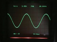
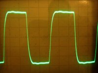
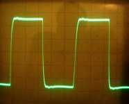
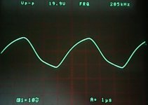
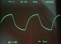
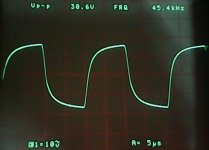
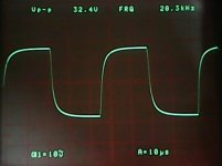
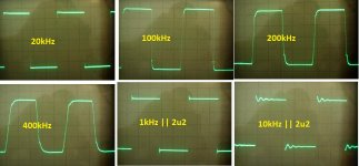
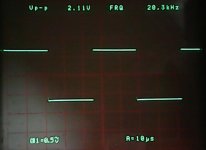
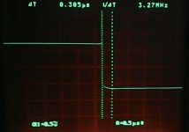
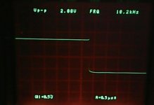
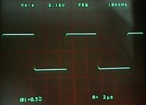
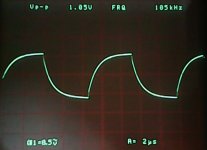
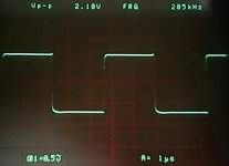
Advanced Symasym tuned a bit... 😉
IPS only! (With input filter: 1k + 68pF)
Just small signal tests... (0.2V/div)
Results: 200kHz, 400kHz, 800kHz.
I hope the OPS will be fast as well... 🙂
IPS only! (With input filter: 1k + 68pF)
Just small signal tests... (0.2V/div)
Results: 200kHz, 400kHz, 800kHz.
I hope the OPS will be fast as well... 🙂
Attachments
hi, my test result ....
do you matching all drivers and output transistor ?
best regard
do you matching all drivers and output transistor ?
best regard
Attachments
-
 IMG_20130108_133433770.jpg137.9 KB · Views: 108
 -
 IMG_20130108_132922290.jpg101.6 KB · Views: 89
 -
 IMG_20130108_132558204.jpg141.1 KB · Views: 98
 -
 IMG_20130108_132222643.jpg88.6 KB · Views: 114
 -
 IMG_20130108_131833332.jpg143.4 KB · Views: 126
 -
 IMG_20130108_131324267.jpg142.4 KB · Views: 141
 -
 Spk output.jpg133.8 KB · Views: 143
 -
 Test signal 1.jpg115.5 KB · Views: 660
Cool, thanks ychan!
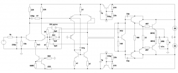
No, I didn't match them.
I attach my final results and the scematic to this thread as well.
They has been taken with input cap 1k-68pF. With 82pF even that small wave disappeared as well around the corners.
What kind of signal generator did you use finally?
No, I didn't match them.
I attach my final results and the scematic to this thread as well.
They has been taken with input cap 1k-68pF. With 82pF even that small wave disappeared as well around the corners.
What kind of signal generator did you use finally?
Attachments
Hi Cortez,
So, why are we worried about the speed of the op amp used for a square wave generator? Because the output can't change fast enough and you end up with a slope instead of an edge. A 555 timer might have been a better choice since it is designed to change output states very quickly. That is what you do want for your signal source for square wave testing. I'm not sure which you are measuring there, 741 or your amplifier??
Did you use the 741 based oscillator for these tests? If so, better redo your work, sorry.
-Chris
Nope, the 741 isn't good for much at higher frequencies. It is a very slow op amp, slewing only about 0.6 V / uSec. That is sslloooww. A TL072 runs about 13 V/uSec, and you can get much faster devices. Even the old LM318 slews around 50 V/uSec, and feed forward compensation can improve that to 70 V/uSec. That's pretty quick!I built it for 1kHz, I dont know wether its ideal for 100kHz range.
So, why are we worried about the speed of the op amp used for a square wave generator? Because the output can't change fast enough and you end up with a slope instead of an edge. A 555 timer might have been a better choice since it is designed to change output states very quickly. That is what you do want for your signal source for square wave testing. I'm not sure which you are measuring there, 741 or your amplifier??
Did you use the 741 based oscillator for these tests? If so, better redo your work, sorry.
-Chris
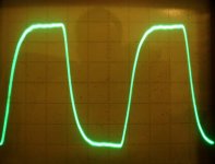
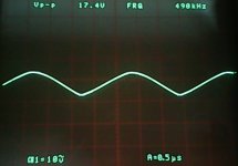
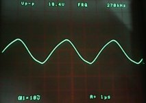
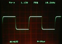
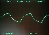
Hi, i'm using Elliott Squarewave Generator (tuned a bit) the link ... Squarewave Testing
the Generated wave
[image][/image] [image][/image]
and below is the image Generated wave before load / loaded with sym
[wiki=[wiki= ]%[/wiki]]%[/wiki]
the Generated wave
[image][/image] [image][/image]
and below is the image Generated wave before load / loaded with sym
[wiki=[wiki= ]%[/wiki]]%[/wiki]
oop's
the Generated wave
and the image Generated wave unload / loaded with sym
anatech is right 741 is too slow, but IMHO i don't think going high SR and high fq will make the amp sound sweet...
[image][/image]
the Generated wave
and the image Generated wave unload / loaded with sym
anatech is right 741 is too slow, but IMHO i don't think going high SR and high fq will make the amp sound sweet...
[image][/image]
Attachments
-
 connected to sym.jpg132.5 KB · Views: 113
 -
 IMG_20130108_131146255.jpg135.4 KB · Views: 112
 -
 zoom in 2.jpg134.3 KB · Views: 109
 -
 zoom in.jpg120.2 KB · Views: 356
 -
 IMG_20130108_132101193.jpg135.5 KB · Views: 113
 -
 IMG_20130108_132136460.jpg142.6 KB · Views: 103
 -
 IMG_20130108_132410090.jpg136.5 KB · Views: 105
 -
 IMG_20130108_132441776.jpg96.8 KB · Views: 109
- Home
- Amplifiers
- Solid State
- Explendid amplifier designed by Michael Bittner, our MikeB