Another important thing missing in this thread is how to get a 36V symmetric power supply? Where would you buy one? How could you make one?
Dual secondary 25Vac transformer, bridge rectifier and two smoothing capacitors
Could you elaborate anything on this? I don't see how such a transformer could get a voltage of 72 V across the two terminals.
In most cases all is ok,except low power.Would it still have a good sound, just with a lower output amplitude? Or would you get distortions and noise?
Could you elaborate anything on this? I don't see how such a transformer could get a voltage of 72 V across the two terminals.
square root (2) = 1.414
2 x 25Vac will give you 2 x 25 * 1.414 Vdc = 2 x 35Vdc (after rectifier and capacitors)
square root (2) = 1.414
2 x 25Vac will give you 2 x 25 * 1.414 Vdc = 2 x 35Vdc (after rectifier and capacitors)
Does the power supply I added as an attachment look good? Only using 25 VAC input instead of 30 VAC.
Attachments
![power-supply-for-amp[1].png](/community/data/attachments/368/368594-7cc48476b6f22176d357c671f05e32e1.jpg?hash=fMSEdrbyIX)
Hi Andrew, I've seen in other posts that you don't agree with the use of c3 and c4.
Can you please explain why.
Also what you you think of the 10nF in parallel to each Bridge diode sometimes seen.
Or is a RC snubber better, if so what values do you use, I'm on 220V mains of that matters,
Thanks
Can you please explain why.
Also what you you think of the 10nF in parallel to each Bridge diode sometimes seen.
Or is a RC snubber better, if so what values do you use, I'm on 220V mains of that matters,
Thanks
Last edited:
Increased risk of ringing in the PSU.
Local Decoupling needs to be at the client circuit, not at the PSU.
Capacitors across the diodes changes the frequency of the ringing.
I guessed at 47nF and 100r, until I read Hagerman.
Local Decoupling needs to be at the client circuit, not at the PSU.
Capacitors across the diodes changes the frequency of the ringing.
I guessed at 47nF and 100r, until I read Hagerman.
Remove C3 and C4.
Find out what your circuit does if one fuse ruptures.
Is it necessary to use a center-tap transoformer on this circuit?
No. You also can use a voltage doubler rectifier circuit. But you'll get higher ripple.Is it necessary to use a center-tap transoformer on this circuit?
\..... Hi radio , I have made some cosmetics on Rudi's PCB wich is the best PCB until now , congrat's to Rudi , I like red colour , nice PCB's . I have tryed to layout for single side , to be available everyone who intend to do this variant .....🙂
Regards Alex .
thank you Alex MM I was looking for this for a while nicely done 🙂
Best Regards
Juan
I guessed at 47nF and 100r, until I read Hagerman.
That article by Jim H. is, unfortunately, badly flawed and his "optimum" values... aren't.
Don't want to criticise, everyone makes mistakes, but it is possible to do better, with less mathematics and measurement, so I would recommend other authors.
Best wishes
David
Ah, i think Carlos forgot to show the upper side of the PCB...
(Of course, this heatsink is too small for longtime full power)
Quick newb question before I start etching and constructing - I can see metal inside the fixing hole of a BD139. So does it need to be electrically isolated from the heatsink? Is the mounting bolt also isolated from the transistor? If so with what?
Quick newb question before I start etching and constructing - I can see metal inside the fixing hole of a BD139. So does it need to be electrically isolated from the heatsink? Is the mounting bolt also isolated from the transistor? If so with what?
Scrub that - with strong light and my glasses on I see the BD139 is isolated from its bolt
The backplate of the To126 is electrically connected to the collector/drain of the device.
The plastic housing provides sufficient clearance between a metal bolt/fixing and the backplate, to be considered electrically isolated.
The plastic housing provides sufficient clearance between a metal bolt/fixing and the backplate, to be considered electrically isolated.
The backplate of the To126 is electrically connected to the collector/drain of the device.
The plastic housing provides sufficient clearance between a metal bolt/fixing and the backplate, to be considered electrically isolated.
Thanks, yes I realized when I turned it around and viewed it from the rear.
Hello
Maybe i`m right here.
My symasym drives my -nuts / crazy / what ever
I have a Stereo amp.
The Problem is: If i connect both cinchgrounds from the 2 pcbs together
(like it is usual with cheap cinch cables) i get hum.
for test i`ve connectet only 1 channel (with same cheap cable) amp is silent.
First i had one PSU for both channels thought this is the Problem.
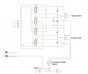
And changed the psu to a "quasi dual mono" -pic-
Problem still remains.
Now i dont know where i should look at?
Someone has an idea / same Problem -> with solution😀
good amp but with HUM no FUN
thank if someone could help me.
Maybe i`m right here.
My symasym drives my -nuts / crazy / what ever
I have a Stereo amp.
The Problem is: If i connect both cinchgrounds from the 2 pcbs together
(like it is usual with cheap cinch cables) i get hum.
for test i`ve connectet only 1 channel (with same cheap cable) amp is silent.
First i had one PSU for both channels thought this is the Problem.
And changed the psu to a "quasi dual mono" -pic-
Problem still remains.
Now i dont know where i should look at?
Someone has an idea / same Problem -> with solution😀
good amp but with HUM no FUN
thank if someone could help me.
Attachments
This symptom is typical of all stereo amplifiers fed from a stereo source that has a common Signal Return for the two channels inside the source.
A single interconnect, be it a coax or twisted pair, makes a single grounding connection along the return conductor.
Equals no interference.
Two interconnects, make a pair of grounding connections into that commoned signal ground. That makes a loop.
If you make the loop smaller the interference pick up is smaller.
If you increase the resistance in the connections at the power amp bigger, then you make the interference current smaller.
Every year we see the Daniel Joffe paper being linked that explains the methods of reducing these interference currents. It was posted (yet again) last week.
I'll try to find it and post a link.
Last edited:
- Home
- Amplifiers
- Solid State
- Explendid amplifier designed by Michael Bittner, our MikeB