
How do I check the 2sk170? They are fets, arent they?
And what values should be between 6 and 700? The resistance? Or should I use the diode-tester of my dmm?
Gesendet von meinem M2 mit Tapatalk
And what values should be between 6 and 700? The resistance? Or should I use the diode-tester of my dmm?
Gesendet von meinem M2 mit Tapatalk
1) Meter Check of a Transistor (JFET) : Junction Field-effect Transistors - Electronics Textbook
2) Yes use the diode testing mode with your DMM!
2) Yes use the diode testing mode with your DMM!
Your rails are @ 35VDC, right? Even if you have a strong PS (trafo + caps)
there will be some losses so an optimistic max Vout = ~30V.
From that and the formula: P = U~2 / R the theoretical numbers are:
Peak (sinus) power:
4R: P = 30*30 / 4 = 225W
8R: P = 30*30 / 8 = 112W
Effective (RMS) power: P = (U/1,4142)^2/R or Upeak/2R
4R: P = 30*30 / 8 = 112W
8R: P = 30*30 / 16 = 56W
But in reality the PS drops more voltages when it's loaded @ Pmax.
You have forgotten the divide by 2 factor in your Pmax formula
Pmax = Vpk² / 2 / Rload.
The 30V you have shown is not Vac. It is Vpk.
If you use the correct Vpk or Vac in the respective formulae you don't end up with confusing results.
Pmax = Idc * Vdc = Idc² * Rload = Vdc²/Rload, when the signal is constant direct current.
Pmax = Iac * Vac = Iac² * Rload = Vac²/Rload, when the signal is a sinewave.
Pmax = Ipk * Vpk = Ipk² * Rload = Vpk²/2/Rload, when the signal is a sinewave.
Pmax = Irms * Vrms = Irms² * Rload = Vrms²/Rload, when the signal is any AC waveform.
Last edited:
😕You have forgotten the divide by 2 factor in your Pmax formula
I calculated both peak and rms max output power.
In the rms I used the "/2" factor.
Isn't it correct this way?
You/we don't need to know peak instantaneous power.😕
I calculated both peak and rms max output power.
In the rms I used the "/2" factor.
Isn't it correct this way?
rms power does not exist.
So, no your methods don't make sense.
Just use the correct units and adopt the appropriate formula.
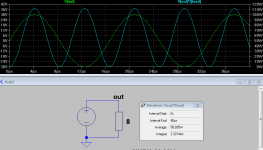
Note in the second to last line of your pic it states
"Average: 58.035W"
no mention of peak instantaneous, nor of rms.
Last edited:
If you know Vpk of the sinewave, then you use:Pmax = Ipk * Vpk = Ipk² * Rload = Vpk²/2/Rload, when the signal is a sinewave.
Pmax = Vpk² / 2 / Rload.
Ok, I think I understand it now:
A question: as I see even in case of a sine wave signal there is difference between the RMS
value (peak * 0.707) and the average value (peak * 0.637). The RMS means the "effective"
value (the same wattage as a DC source would be give). Is there a case or at least
a calculation where the average value should be used instead of the RMS?
- DC part is trivial
- in case of sine wave there are simple formulas to describe the relation between the peak and the RMS value
- on a random AC signal the peak power is meaningless and the RMS could be measured/simulated
- in the power equation the voltage is powered by 2 so the RMS voltage in this sense does not mean RMS power, right?
An externally hosted image should be here but it was not working when we last tested it.
A question: as I see even in case of a sine wave signal there is difference between the RMS
value (peak * 0.707) and the average value (peak * 0.637). The RMS means the "effective"
value (the same wattage as a DC source would be give). Is there a case or at least
a calculation where the average value should be used instead of the RMS?
DC is not trivial. It's all they had when they invented the system of describing Amperes and Volts and Watts.
It's the easy way to get you started, if you have forgotten and need to get there from first principles.
They then had to work out what needed to be done to get the correct relationship when something other than constant DC became available.
How they invented sqrt(2) as the required factor is the clever bit.
If you need the correct heating effect of a current, or voltage, then you must use the rms current or the rms voltage. It is the heating effect that is important.
Average may be what is required to rescale a moving iron galvanometer to read correctly since it can't read an rms value.
If you had a square wave that had real corners (infinite frequencies) then average can be calculated.
Similarly for a sawtooth or triangle waveform.
A trapezoidal waveform (a squarewave with sloping ramps) could also be averaged.
Last edited:
All small transistors seem to be OK.
The voltage drop across R7 is 3mV/0,01mV.
DC-Offset is now about 0,05VDC (0,1V yesterday) although I didnt change anything.
The voltage drop across R7 is 3mV/0,01mV.
DC-Offset is now about 0,05VDC (0,1V yesterday) although I didnt change anything.
And what about the resistance values of the resistors in the section I marked?
Wherever you can, do not measure on the 2 legs of the resistor but at a next node where it goes.
(With this method you can also check the solderigs in the same time...)
Wherever you can, do not measure on the 2 legs of the resistor but at a next node where it goes.
(With this method you can also check the solderigs in the same time...)
I still listen to my Symasym from time to time. Michael got it right.
You probably need a scope to see oscillation but since your bias is staying steady you are probably OK. Oscillation will generally cause heating problems and you will often hear some hash or hissing. Maybe someone else will have another way to check for oscillation when not using a scope.
Hey terry follow the thread stopped around 220 mark and now....you sometimes listen to the symasym?! what did i miss...
Lawrence
I've seen many examples of oscillation where there was no excess heating. This looks like a pretty stable design though.
I think this amp uses a hidden and confusing form of TPC.
I think this amp uses a hidden and confusing form of TPC.
I think I found the error. R8 seems to be 68 instead of 680 Ohm.
But the colourcode of R8 and R9 is the same.
But the colourcode of R8 and R9 is the same.
think I found the error. R8 seems to be 68 instead of 680 Ohm.
But the colourcode of R8 and R9 is the same.
Edit: R8 had 680 Ohm, but there was a short between the base of Q6 and the collector. So I meassured R10.
But the colourcode of R8 and R9 is the same.
Edit: R8 had 680 Ohm, but there was a short between the base of Q6 and the collector. So I meassured R10.
After removing the really small part of a copper wire (of a desoldering wick) I am able to adjust the bias.
The dc-offset is now 6mV.
The dc-offset is now 6mV.
- Home
- Amplifiers
- Solid State
- Explendid amplifier designed by Michael Bittner, our MikeB