You can either put caps on the frontend-CAP-Multiplier - jumpers (means: disabling the CAP-multiplier; the frontend-voltage will then be taken from the backend-rail)
or leave the cap (activating the frontend-CAP-Multiplier).
In any way: the 2 LEDs, signalling that the frontend-voltage is present, must shine.
Remove the fuses of the onboard-fuseholders.
Use 10 Ohm/0.25W resistors instead of the fuses (connect croco-clips with the 10 Ohm resistors between it to the fuses' cases).
Turn the trim-potentiometer to its maximum value of 500 Ohm.
The bias-current will be "(near) zero" then.
Insert the bulb-check into the transformer's primary winding.
Power On.
Do the 10 Ohm resistors begin to smell?
They shall not, since the frontend is using <15mA of current and there is "no bias current".
If they do not smell: measure the frontend-voltages.
If the frontend-voltages are o.k., remove the bulb-test, remove the 10 Ohm resistors and re-insert the fuses into the fuse-holders.
Power on and try to adjust the bias current by turning the trim-potentiometer.
Best regards - Rudi
P.S.: Btw: this all is explained/illustrated in the Builder's Manual. Take your time and read it!
You can either put caps on the frontend-CAP-Multiplier - jumpers (means: disabling the CAP-multiplier; the frontend-voltage will then be taken from the backend-rail)
or leave the cap (activating the frontend-CAP-Multiplier).
In any way: the 2 LEDs, signalling that the frontend-voltage is present, must shine.
Remove the fuses of the onboard-fuseholders.
Use 10 Ohm/0.25W resistors instead of the fuses (connect croco-clips with the 10 Ohm resistors between it to the fuses' cases).
Turn the trim-potentiometer to its maximum value of 500 Ohm.
The bias-current will be "(near) zero" then.
Insert the bulb-check into the transformer's primary winding.
Power On.
Do the 10 Ohm resistors begin to smell?
They shall not, since the frontend is using <15mA of current and there is "no bias current".
If they do not smell: measure the frontend-voltages.
If the frontend-voltages are o.k., remove the bulb-test, remove the 10 Ohm resistors and re-insert the fuses into the fuse-holders.
Power on and try to adjust the bias current by turning the trim-potentiometer.
Best regards - Rudi
P.S.: Btw: this all is explained/illustrated in the Builder's Manual. Take your time and read it!
Hi Rudi, the 10Ohms resistors are in my Fuses already and I red your manual as well don't worry 🙄
Btw, I saw in your built that you used insulater for your screws on the MUR820 diodes as well, so I changed this as well. Then I tested it again and then the lightbulb slightly goas out and my relais K1 clicked. The status LED is on as well, but the LED1 and 2 or off ... The 10Ohm resistors for testing dont smell or are hot.
When I measure the voltage across the 10Ohms there are only 0,3V instead of 1,5 as shown in your manual Rudi. So there must be another failure I assume ?
This is quite a progress!
The bulb test will glow brightly during the 1st second after Power-On, when the inrush-current saturates your transformer and will then weaken.
This is "works as designed".
Did I write about a 1.5V drop across the 10Ohm resistor?
Calculate yourself! You measure a voltage drop of about 0.3V. This means that a current of about 30mA is flowing through the 10Ohm resistor. This is a value that I expect.
But LED1 and LED2 must shine anyway! Did you solder them correctly? The anode has the longer leg. Measure the frontend-voltages please!
Best regards - Rudi
This is quite a progress!
The bulb test will glow brightly during the 1st second after Power-On, when the inrush-current saturates your transformer and will then weaken.
This is "works as designed".
Did I write about a 1.5V drop across the 10Ohm resistor?
Calculate yourself! You measure a voltage drop of about 0.3V. This means that a current of about 30mA is flowing through the 10Ohm resistor. This is a value that I expect.
But LED1 and LED2 must shine anyway! Did you solder them correctly? The anode has the longer leg. Measure the frontend-voltages please!
Best regards - Rudi
Okay nice to hear, well I measured with my scope now and I think all Voltages are correct, because I measured -36V on the negative side and ~38V on the postive side. On the LED's I measured 3,2V wich I think is a bit too high ? I use 27V transformers could it be that I roasted them because of too high Voltage ?
My LED D80 on the PNP side shines as well but D81 not. What should I do next ?
Regards
It's working now !!! I have under 0,3 mV on X1 and GND. The Sound is fantastic ! But I have one last question. Do I need a limiter or something ? Because I don't know how loud I can make this thing.
I have a 100KOhm Alps Poti as Volumecontrol.
im building this amp with regulated 35.5v vcc and vee
my amp cliping @69watt rl 4ohm what wrong
sorry for my bad language
my amp cliping @69watt rl 4ohm what wrong
sorry for my bad language
Clipping at 5.87A may be your regulator's current limit. You probably want at least a 15A regulator.
Clipping at 5.87A may be your regulator's current limit. You probably want at least a 15A regulator.
my switching converter no current limiting no voltage drop using sg3525 push pull conveter and 4n35 optocopler
using 40hz sinewave cliping @16.7 volt rms using ear methode rl 4 ohm
Hi guys, I think I have a problem with my output resistor. It becomes very hot and it smoked for a short time. Can I change it to 5W or do I hear my music just too loud ?
My Heatsink is not very hot i can touch it with my fingers when I hear very loud music. But my question is how do I know when it's enough ?
I know bad question ... but can anyone help me ?
My Heatsink is not very hot i can touch it with my fingers when I hear very loud music. But my question is how do I know when it's enough ?
I know bad question ... but can anyone help me ?
Hi guys, I think I have a problem with my output resistor. It becomes very hot and it smoked for a short time. Can I change it to 5W or do I hear my music just too loud ?
My Heatsink is not very hot i can touch it with my fingers when I hear very loud music. But my question is how do I know when it's enough ?
I know bad question ... but can anyone help me ?
I forgot to mention that I use my laptop output as Sound source. Could it be that this Output is Pre amplifier and that's the source of my Problem ?
Output resistors getting hot is an indication of oscillation
Is there anything I can do to prevent the oscillation ? Or is the Oscillation the result of clipping ?
It could be oscillation or it could be ultrasonic noise from a computer or other output because of SMPS. This can happen if your ground connection isn't very good, or your source may just be very noisy. Does it still get hot with the source disconnected or volume pot at zero?
Trying to tame oscillation with no oscilloscope is like trying to find a black cat in a dark room (especially if it's not there).
It could be oscillation or it could be ultrasonic noise from a computer or other output because of SMPS. This can happen if your ground connection isn't very good, or your source may just be very noisy. Does it still get hot with the source disconnected or volume pot at zero?
If it's disconnected it's only warm i can Touch it for minutes...
Trying to tame oscillation with no oscilloscope is like trying to find a black cat in a dark room (especially if it's not there).
I have a scope here,can you give me help how I measure the oscillation ? Which Mode on the scope etc. I,m totally new in this Kind of meaurements
Hi guys!
Going back to my SymAsym build, I can't make the bias adjust to work
It worked the first time I power the amp, set it to a low 20mv across both 0.22r just for a test run. Following the other day I cannot measure any dc voltage across the re and at the bases of the drivers, totally zero, none. Playing music with it, it will work and I can get DC voltages but without music it goes back to zero. I thought I messed up the vbe 1k trimmer because I am hearing faint clicks while repeatedly doing the process.
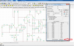
I decided to run a simulation of the amp and made new values at the bias circuit for use with a 5k trimmer (believing I busted my last 1k trimmer but never bothered to check it off board) but after placing the new values on board and adjusting the trimmer per simulation result, it still didn't work. 😕
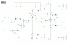
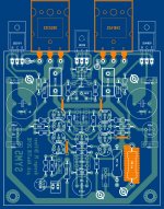
Attached is a revised pcb lay-out and my schematic. Notice the addition of a small resistor at the ltp emitters (R36), this reduces a few CCS current because DC transistor condition in sim shows that one trannie is hot (Q6 tied to 22k-ground). The 2.2k addition seemed to lower the THD figure (in simulation).
My actual build is working nicely, sonic is very good, dead silent and no turn on/off thump... I just can't figure out why biasing stopped working or is not working. I have check the drivers, vbe bias and output trannies but found no indication of any defects....any ideas what has gone wrong and where to check for possible fault?
BTW I am using c5200/a1943 and c5171/a1930(drivers), DC offset is -12mv (no matching done).
Regards!
Albert
Going back to my SymAsym build, I can't make the bias adjust to work
It worked the first time I power the amp, set it to a low 20mv across both 0.22r just for a test run. Following the other day I cannot measure any dc voltage across the re and at the bases of the drivers, totally zero, none. Playing music with it, it will work and I can get DC voltages but without music it goes back to zero. I thought I messed up the vbe 1k trimmer because I am hearing faint clicks while repeatedly doing the process.
I decided to run a simulation of the amp and made new values at the bias circuit for use with a 5k trimmer (believing I busted my last 1k trimmer but never bothered to check it off board) but after placing the new values on board and adjusting the trimmer per simulation result, it still didn't work. 😕
Attached is a revised pcb lay-out and my schematic. Notice the addition of a small resistor at the ltp emitters (R36), this reduces a few CCS current because DC transistor condition in sim shows that one trannie is hot (Q6 tied to 22k-ground). The 2.2k addition seemed to lower the THD figure (in simulation).
My actual build is working nicely, sonic is very good, dead silent and no turn on/off thump... I just can't figure out why biasing stopped working or is not working. I have check the drivers, vbe bias and output trannies but found no indication of any defects....any ideas what has gone wrong and where to check for possible fault?
BTW I am using c5200/a1943 and c5171/a1930(drivers), DC offset is -12mv (no matching done).
Regards!
Albert
Attachments
It is in one channel only, the other channel is still incomplete.
Vbe of Q8 - you mean measured voltage? I made a resistance check between the trimmer and collector of Q8. also trimmer to emitter of Q8. Result is confusing as the trimmer resistance does not seem to add to the series resistor of base to collector and also base to emitter.
Vbe of Q8 - you mean measured voltage? I made a resistance check between the trimmer and collector of Q8. also trimmer to emitter of Q8. Result is confusing as the trimmer resistance does not seem to add to the series resistor of base to collector and also base to emitter.
Are you having this problem in more than one channel? What is the Vbe of Q8?
just made a measurement at this moment voltage bet base and emitter of Q8 starts at 0.5mv then drops to zero. when a player is plugged in there is a 0.7mv across both output re.
just made a measurement at this moment voltage bet base and emitter of Q8 starts at 0.5mv then drops to zero. when a player is plugged in there is a 0.7mv across both output re.
To give a short answer the value of R13 is too high to allow enough current to flow from the emitter of Q8 and out of the base - so this transistor is not able to turn on. In that case ( if on) it would have a base to emitter voltage drop of close to 0.6 volts.
I suggest you review the values of R13, X1, and R35 looking at various versions of this circuit posted on this thread. In early versions R13 is 2k2.
- Home
- Amplifiers
- Solid State
- Explendid amplifier designed by Michael Bittner, our MikeB