
hello Rudi
I have a question, those Q80,81 they work as voltage regulator to feed with clean voltage to the IPS driver right? I'm just guessing 🙂
Regards
Juan
I have a question, those Q80,81 they work as voltage regulator to feed with clean voltage to the IPS driver right? I'm just guessing 🙂
Regards
Juan
Must I screw the Transistors Q80 and Q81 on the heatsink too ? Or is it enough to solder it directly on the PCB with air around it ?
I dont think so: they just have a few mA current and <1V voltage drop as a regulator.
So the dissipation is < 100mW...
Hey guys, I have an another question...
I have 2, 200VA Toroid Transformers here with 3 Pins out blk/red/vio (SW/RT/VIO) and now how do I connect them to the SymAsym ? I would say RT is my GND (0V), SW +27V and VIO -27V ? Or am I wrong ?
I have 2, 200VA Toroid Transformers here with 3 Pins out blk/red/vio (SW/RT/VIO) and now how do I connect them to the SymAsym ? I would say RT is my GND (0V), SW +27V and VIO -27V ? Or am I wrong ?
Attachments
It's a dual Primary.
Your first question since it is potentially more damaging when you get it wrong is:
How do I wire up the dual primary?
Fit the three leads into separate terminals of an insulated terminal block.
Power on via Mains Bulb Tester.
Measure across the three leads and record the AC volts. Three measurements.
Present your results.
It's a dual Primary.
Your first question since it is potentially more damaging when you get it wrong is:
How do I wire up the dual primary?
Fit the three leads into separate terminals of an insulated terminal block.
Power on via Mains Bulb Tester.
Measure across the three leads and record the AC volts. Three measurements.
Present your results.
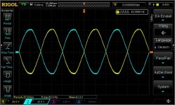
Well I measured it with my Scope. CH1 (yellow) is measured between the Black and the Red wire and CH2 (blue) is measure between Violet and Red.
Is black then -27V because it's a Cosinus (180°) ? And violet +27V because of a normal Sinus ? (0°)
Between Black and Violet i measured 58V with my DMM
Do you need anything else ?
Attachments
Last edited:
As you measure 2X27V A.C, NOT + OR -, then you have connect primary on the right way.Well I measured it with my Scope. CH1 (yellow) is measured between the Black and the Red wire and CH2 (blue) is measure between Violet and Red.
Is black then -27V because it's a Cosinus (180°) ? And violet +27V because of a normal Sinus ? (0°)
Between Black and Violet i measured 58V with my DMM
Do you need anything else ?
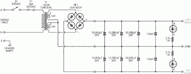
Transformer voltage is A.C.
You must use a rectifier connected to secondary coil to take D.C voltage.
Then using big electrolytic capacitors this D.C filtered enough.
The amplifier will be connected after capacitors
Look an examble here.
The only way to connect the A.C voltage to an amplifier is the rectifier and filter capacitors are included on amplifier pcb.like this on post #4061.
Attachments
Last edited:
As you measure 2X27V A.C, NOT + OR -, then you have connect primary on the right way.
Transformer voltage is A.C.
You must use a rectifier connected to secondary coil to take D.C voltage.
Then using big electrolytic capacitors this D.C filtered enough.
The amplifier will be connected after capacitors
Look an examble here.
The only way to connect the A.C voltage to an amplifier is the rectifier and filter capacitors are included on amplifier pcb.like this on post #4061.
Yes this is clear for me i'm just asking me because of the pinout of the transformers.
Thanks everyone
You omitted to tell us you wired two of the secondary tappings together.As you measure 2X27V A.C, NOT + OR -, then you have connect primary on the right way.
Transformer voltage is A.C.
You must use a rectifier connected to secondary coil to take D.C voltage.
Then using big electrolytic capacitors this D.C filtered enough.
The amplifier will be connected after capacitors
Look an examble here.
The only way to connect the A.C voltage to an amplifier is the rectifier and filter capacitors are included on amplifier pcb.like this on post #4061.
How can we approve your wiring if you don't tell us what you are planning to do, or have done?
And take on board that AC does not have +ve nor -ve.
AC1, AC2, AC3, AC4 would be the four tappings. Assign those colour codes.
Is AC1 and AC2 on the same winding?
Is AC3 and AC4 on the same winding?
Is AC1 isolated from AC3?
Last edited:
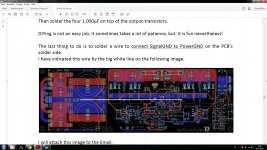
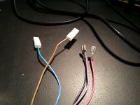
It is always good practice to separate "Power GND" from the frontend's "Signal GND".
Solder a wire as shown in the Builder's manual (in your picture).
Regards - Rudi_Ratlos
Solder a wire as shown in the Builder's manual (in your picture).
Regards - Rudi_Ratlos
It is always good practice to separate "Power GND" from the frontend's "Signal GND".
Solder a wire as shown in the Builder's manual (in your picture).
Regards - Rudi_Ratlos
Okay I soldered a wire between PWR GND ans SGL GND. But I have an another Problem now. I checked the whole PCB if I made some failures but there isn't. When I connect my Transformer with a 30W Bulb (for current restriction) on the PCB the Bulb shines, so there must be a short somewhere ... I connected it for 5 sec. ca. Then I connected a Power Supply (+20V -20V) on the Pins from SV1, the LED's D80,81 shined so the negative and positive Voltage is there. Then I tried to decrease the Poti R18 but on MP1 and MP2 is just 0mV. Is there anything I can check now where the failure could be ?
Please help 🙁
Leave the light bulb in place and adjust the bias until the light goes out.
With the Resistor R18 ?
Leave the light bulb in place and adjust the bias until the light goes out.
But must the LED1 and LED2 shine ? because when I connect the Transformer there shines nothing of these 2 LED's, just the 30W bulb itself... I don't want to destroy my PCB so I'm asking before 😕
for first power up set the output bias voltage to near zero. This gets the output bias current to zero.
Short the input and disconnect any dummy output load and use the Bulb Tester to power ON.
Measure voltages of the PSU and of the amplifier to prove that all is wired correctly.
When you are sure that all these voltages are close to correct, then power OFF, disconnect the Bulb Tester and power ON direct to mains supply.
Remeasure voltages to check all is working correctly.
Measure output DC and AC.
Start setting the output bias until to have a small output bias current. recheck DC & AC output voltages. Gradually increase the bias current by adjusting the bias voltage. As you get close to final, leave the amp to heatsoak. Recheck output bias and make a small adjustment to the now warm output stage. recheck output AC & DC. Heatsoak, adjust as necessary.
Power OFF leave to go completely cold.
Attach DC voltmeter (better with an analogue-needle type meter) across the output. Power ON and note how big the output pulse is during start up and warm-up.
for first power up set the output bias voltage to near zero. This gets the output bias current to zero.
Short the input and disconnect any dummy output load and use the Bulb Tester to power ON.
Measure voltages of the PSU and of the amplifier to prove that all is wired correctly.
When you are sure that all these voltages are close to correct, then power OFF, disconnect the Bulb Tester and power ON direct to mains supply.
Remeasure voltages to check all is working correctly.
Measure output DC and AC.
Start setting the output bias until to have a small output bias current. recheck DC & AC output voltages. Gradually increase the bias current by adjusting the bias voltage. As you get close to final, leave the amp to heatsoak. Recheck output bias and make a small adjustment to the now warm output stage. recheck output AC & DC. Heatsoak, adjust as necessary.
Power OFF leave to go completely cold.
Attach DC voltmeter (better with an analogue-needle type meter) across the output. Power ON and note how big the output pulse is during start up and warm-up.
I try to explain it in my words if I connected it all correctly for the adjusting phase.
1. I connected Pin 1 and 2 of the CAP multiplier for smoothing my input voltage (described in the manual from Rudi)
2. I connected a lightbuld between L of my Schukosocket (230V) and L of my Transformer primary (In series for limiting the current 30W)
3. Then I connected the secondaries to my SymAsym PSU
4. When I connect the Socket to 230V, my 30W lighbulb shines but the Status LED's from the PSU not ... ???
5. Then I decrease the resistance of R18 till the lightbulb doesn't shine anymore ?
Or have I forgot something to do ?
Did you Bulb check your transformer wiring?
Did you Bulb check your rectifier wiring?
Did you Bulb check your smoothing capacitor wiring?
Do it all in stages instead of connecting 27stages at once and hoping we can work out for you which one of those might be faulty !
Did you Bulb check your rectifier wiring?
Did you Bulb check your smoothing capacitor wiring?
Do it all in stages instead of connecting 27stages at once and hoping we can work out for you which one of those might be faulty !
- Home
- Amplifiers
- Solid State
- Explendid amplifier designed by Michael Bittner, our MikeB