Ohhh this is very nice. I was trying to loft from the wood to the driver. I see you lofted using a rail from the bottom and then used a revolve to cut out the tweeter. Very clever.That will make a difference but it is not likely to be a positive one. Creases are not good and making something like a waveguide start at the edge of the tweeters faceplate is also a way to introduce negative diffraction effects.
This image shows where the edge rounding starts and as close to the drivers as possible is a good idea.
View attachment 1356901
For a non waveguided approach this is an option. The ridges and sharp corners are not ideal and their diffraction effects can still be seen, that can be avoided by rounding all the sides as is shown in the waveguide version above.
View attachment 1356902
I'm going to try this tomorrow
I've been thinking that, perhaps, the best way to proceed in this vein is to build on the seminal work of Olson that has been referenced here and which gets an airing every month or two by Dave (planet10).Let's do some science!
If this is to be done in the digital realm, what might be done is to fill in the gaps between his standard shapes and, as proposed, add new profiles to his edge treatments. To be understood in the context of Olson's curve data the current modeling should replicate his presentation. Perhaps a proof of concept would be to first align the digital models with his built ones.
Some obvious extensions would be a combination of his "B" and "C" enclosures in a "bullet" shape that eliminates the edge that made "B" worse than "A" -- figures 6 and 7. And replacing "B" with the front half of "G" to form a teardrop and varying the height of the rear cone might provide some useful information.
Varying driver placement with respect to baffle edges could use some investigation... again referenced to Olson's fundamentals.
And then there is the issue of additional edge profiles. Essentially, Olson tried one alternative to "the best edge is no edge" (enclosure "A") -- the chamfered edges of enclosures "J" and "L". I too remember the Speaker Builder article that recommended a large-radius edge. That and the cabinets of Thiel loudspeakers prompt me to wonder then about a parabolic (elliptical) edge and whether the thumbnail profile might be a potentially doable -- or even optimal -- treatment... one that wouldn't require heroic woodwork to build a large curve. I never had the equipment or the opportunity to try it out.
The availability of CNC and 3D printing might make the option of large thumbnail routing less attractive -- or even moot -- but an investigation of varying elliptical ratios would still be of interest to the numeric manufacturer and add a valuable richness to Olson's basics.
Shouldn’t the top be rounded too. Like the Theil? Rounding the sides and top but not the top side edges is maybe not thinking the problem through? I’ve always thought that since sound travels at the speed of sound that loudspeakers should be built more like fighter planes from WWII. Smooth curves no obvious angles or sharp edges.That will make a difference but it is not likely to be a positive one. Creases are not good and making something like a waveguide start at the edge of the tweeters faceplate is also a way to introduce negative diffraction effects.
This image shows where the edge rounding starts and as close to the drivers as possible is a good idea.
View attachment 1356901
For a non waveguided approach this is an option. The ridges and sharp corners are not ideal and their diffraction effects can still be seen, that can be avoided by rounding all the sides as is shown in the waveguide version above.
View attachment 1356902
My wife can’t stand the idea of a loudspeaker with a rounded top, ‘where do you put your wine glass?‘ (eye roll)

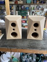
I can make shapes and run them. Ideally I would use a smaller driver as the smaller the enclosure the less material I need to use.I've been thinking that, perhaps, the best way to proceed in this vein is to build on the seminal work of Olson that has been referenced here and which gets an airing every month or two by Dave (planet10).
If this is to be done in the digital realm, what might be done is to fill in the gaps between his standard shapes and, as proposed, add new profiles to his edge treatments. To be understood in the context of Olson's curve data the current modeling should replicate his presentation. Perhaps a proof of concept would be to first align the digital models with his built ones.
Some obvious extensions would be a combination of his "B" and "C" enclosures in a "bullet" shape that eliminates the edge that made "B" worse than "A" -- figures 6 and 7. And replacing "B" with the front half of "G" to form a teardrop and varying the height of the rear cone might provide some useful information.
Varying driver placement with respect to baffle edges could use some investigation... again referenced to Olson's fundamentals.
And then there is the issue of additional edge profiles. Essentially, Olson tried one alternative to "the best edge is no edge" (enclosure "A") -- the chamfered edges of enclosures "J" and "L". I too remember the Speaker Builder article that recommended a large-radius edge. That and the cabinets of Thiel loudspeakers prompt me to wonder then about a parabolic (elliptical) edge and whether the thumbnail profile might be a potentially doable -- or even optimal -- treatment... one that wouldn't require heroic woodwork to build a large curve. I never had the equipment or the opportunity to try it out.
The availability of CNC and 3D printing might make the option of large thumbnail routing less attractive -- or even moot -- but an investigation of varying elliptical ratios would still be of interest to the numeric manufacturer and add a valuable richness to Olson's basics.
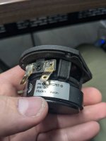
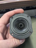
I have the one driver here I can use. I think this is 2"
Would be even better to use a 1" driver.
Attachments
Ha, my goal of rounding the top isn't directivity/diffraction related but to keep the wife and kids from using speakers as a shelf for whatever they happen to need to set down at the moment.My wife can’t stand the idea of a loudspeaker with a rounded top, ‘where do you put your wine glass?‘ (eye roll)
KEF engineers have long tradition with diffraction control. A. Jones was one of them and now J. Oclee-Brown.
KEF R5 coaxial MT with rounded frame, but the box has sharp edges. Excellent outcome, but not perfect! https://www.erinsaudiocorner.com/loudspeakers/kef_r5_meta/

A good bad example are B&W speakers with more or less teardrop enclosures for M and T https://www.stereophile.com/content/bowers-wilkins-801-d4-signature-loudspeaker-measurements


So, there are many way to skin a cat
KEF R5 coaxial MT with rounded frame, but the box has sharp edges. Excellent outcome, but not perfect! https://www.erinsaudiocorner.com/loudspeakers/kef_r5_meta/
A good bad example are B&W speakers with more or less teardrop enclosures for M and T https://www.stereophile.com/content/bowers-wilkins-801-d4-signature-loudspeaker-measurements
So, there are many way to skin a cat
I once chased some sibilance in a small speaker. The low xo, small baffle size, and roundover seemed to be the cause. The round edge of equal distance from the driver caused what I call a "disco ball decay". You get a nice and even power but humps in the decay.
from an old post: A 2d ripple of baffle shapes (this is assuming the driver is a point source)
.png")
from an old post: A 2d ripple of baffle shapes (this is assuming the driver is a point source)
Thats very interesting and a great help to visualize what is going on. The diamond box makes my head hurt.
The top edge above a tweeter is surprisingly tolerant to less than ideal shapes. Thinking the problem through does not always lead to good answers, acoustics is an unintuitive discipline. There are a lot of interactive factors that can change the result. The best results can be from accidents as they don't immediately look as if they would be a good idea, but actually are.Shouldn’t the top be rounded too. Like the Theil? Rounding the sides and top but not the top side edges is maybe not thinking the problem through? I’ve always thought that since sound travels at the speed of sound that loudspeakers should be built more like fighter planes from WWII. Smooth curves no obvious angles or sharp edges.
A shape that is designed to have no diffraction will also have no directivity. In a design where higher directivity is desired the diffraction needs to be managed rather than eliminated.
Vivid Audio speakers designed by Laurence Dickie (B&W Nautilus) take the smooth surfaces all around approach and measure surprisingly well for very expensive speakers.
I think this is an important point to consider that a speaker design is an overall collection of compromises and trying to maximise one aspect might not give the best overall result.The round edge of equal distance from the driver caused what I call a "disco ball decay". You get a nice and even power but humps in the decay.
hmmm... is that strictly true for the system?A shape that is designed to have no diffraction will also have no directivity.
The drivers will demonstrate directivity -- beaming -- depending on their dimensions, no?
No which is why I said shape and not system.hmmm... is that strictly true for the system?
got you
from the discussion I understood that we were only managing diffraction to minimize undesirable anomalous effects... comb filter stuff.... not to generate directivity ques.
from the discussion I understood that we were only managing diffraction to minimize undesirable anomalous effects... comb filter stuff.... not to generate directivity ques.
Once you explore how the entire shape of a speaker affects it's response you can see how there are more factors available to tailor the response to a target as well as reduce obvious issues. For a long time on axis measurements were all that DIY designers looked at, diffraction related ripple is very obvious in those. Once you have a full polar measurement set a different picture emerges.
What happens and why after the baffle ends isn't that well understood across the board.
There is an example here of how the overall directivity and smoothness of response can be changed quite considerably from the enclosure shape.
https://www.diyaudio.com/community/...ver-full-range-line-array.242171/post-6524791
I built the uglier looking one as I didn't appreciate or understand the impact of cabinet shape at the time. The 3 to 5K region has always been tricky to equalise and the graphs show why.
I've been thinking that, perhaps, the best way to proceed in this vein is to build on the seminal work of Olson that has been referenced here and which gets an airing every month or two by Dave (planet10).
Olson's work is an important contribution and a good starting place for diy'ers. Modern analytical tools may make it possible to dive much further down the rabbit hole, but as others have mentioned, will it be audible? There is much more that goes into an accurate loudspeaker system. Rigidity, damping, diffraction control are factors in lowering the acoustic noise floor and allowing superior modern drivers the best conditions to perform to their potential. I place diffraction control high in priority for any diy speaker project I undertake and as a positive side effect, my preferred chamfered baffles result in a relatively massive, stiff baffle.And then there is the issue of additional edge profiles. Essentially, Olson tried one alternative to "the best edge is no edge" (enclosure "A") -- the chamfered edges of enclosures "J" and "L".
As to audibility, my subjective experience in over 10 years of building speakers that attempt to ameliorate the negative effects of enclosure edge diffraction, is that the small details in the audio become more easily heard, sometimes for the first time in familiar recordings. Of course other factors contribute.
Attachments
I remember reading that and wondering why did a 6mm chamfer make that difference? I like the egg shaped enclosures. Might be difficult for the average guy to build though.Once you explore how the entire shape of a speaker affects it's response you can see how there are more factors available to tailor the response to a target as well as reduce obvious issues. For a long time on axis measurements were all that DIY designers looked at, diffraction related ripple is very obvious in those. Once you have a full polar measurement set a different picture emerges.
What happens and why after the baffle ends isn't that well understood across the board.
There is an example here of how the overall directivity and smoothness of response can be changed quite considerably from the enclosure shape.
https://www.diyaudio.com/community/...ver-full-range-line-array.242171/post-6524791
I built the uglier looking one as I didn't appreciate or understand the impact of cabinet shape at the time. The 3 to 5K region has always been tricky to equalise and the graphs show why.
View attachment 1357303
View attachment 1357304
@mhenschel@Bon
... the obvious focus for me was to investigate the mitigation of diffraction
Olson's work is not the last word and I am by no means against further investigation of the effects of diffraction. I just wanted to express the opinion, based on my diy experience, that there is unlikely to be an "aha, that's it" moment. The diffraction effects are subtle and incremental and in practical application need to be considered together with the other artefacts that contribute to an enclosure "noise floor".
- Home
- Loudspeakers
- Multi-Way
- Edge Diffraction Testing - Shapes