That simulation seems to be focused in on finding directivity, not diffraction.
In any case, a computer is willing to help you waste time at an accelerated rate. It depends what you put into it.
In any case, a computer is willing to help you waste time at an accelerated rate. It depends what you put into it.

For sure, you could optimize for anything. For low diffraction you can start by putting a point source on a big sphere and take that as no diffraction in listening window reference. Even then you'll notice the sound diffracts all around the device, and that's the base line, best performance you'll get unless very big structure and the sound attenuates enough when it comes around. Now you have good baseline to compare against.
But, it depends what you consider bad diffraction and what good, mabat's waveguides use diffraction to increase DI at the low end, but the profile is such that it happens mostly only there, with some minor ripple on top octaves on the earlier models but the recent ones have about no visible ripple left in the frequency response graphs he has been posting. Since diffraction would make frequency response vary per observation angle, you can monitor this. If all your angles have uniform response you can be sure there is no, or very little secondary sound happening, which means diffraction. If there was secondary sound louder than ~-40dB you'd see ripple on the frequency response. If the secondary sound is at low frequency, around the "bafflestep" you see the polar graph lines diverge quite fast, iow make small jump into DI. When there is none the transition is gradual, compare to point source on a sphere, if yours differs you've got some diffraction and could determine if it's fine or not, knowing your own target performance.
-40dB secondary sound makes roughly ~0.1dB ripple which would be barely visible on most graphs posted. -20dB secondary sound would make +-1dB ripple which should be visible on most graphs seen on forums. Can we hear this stuff is another question, but it is sure sign any secondary sounds are very low in level when there is no visible ripple, lower than if there was ripple visible, thus less audible. I bet computer could optimize even for -60dB secondary sounds, but how valid is that, can our manufacturing tolerances do that small detail? Perhaps, so why not try, it's roughly the same cost to manufacture better or worse waveguide profile, difference in physical structure can be relatively small.
Last edited:
I and others have posted plently of these in different threads but it becomes hard to keep track of them all for reference.
So is it time to bring the 3d stuff together in one place along with some open source tools so that people with an interest in the engineering details of their speaker designs can work together to push things forward?
I have just spent a day getting the old and I think now abandoned acousto BEM code to compile against current versions of libraries like MPI and ported it to run on Windows rather than just unix (still has a bug but runs). It needs refactoring to create a sane set of apis in order to support adding the features we would need. It should only take a day or two given it is an already working code. It would still lack some of the features in akabak but being open source and cross platform it is likely to be a better base for going forward with the BEM aspect of a group project.
Not sure this is the right place for the discussion. I posted something similar in a thread on on-wall speakers without sparking any interest.
I don't see why not, Open Source software is always good to have. I think this may be a case of build it and they will come, asking for a show of hands without some pictures and graphs to go with it tends to raise very few.So is it time to bring the 3d stuff together in one place along with some open source tools so that people with an interest in the engineering details of their speaker designs can work together to push things forward?
I don't see why not, Open Source software is always good to have. I think this may be a case of build it and they will come, asking for a show of hands without some pictures and graphs to go with it tends to raise very few.
A few years ago when jeff bagby's software was reaching the end of it's life I started a "virtuixcad" cross platform open source project and nobody came. I did pretty much everything wrong in terms of attacting people and also had no interest in the coding as a personal project rather than a group project. It was informative and one of things I learnt was that people won't necessarily come. Acousto has been a dead project for 10 years with, as far as I can tell, nobody joining although the original authors don't seem to have encoraged contributions.
If one has a table saw with a tilting blade they can be simply (if slowly!) accomplished with a number of angled cuts and some block sanding; a near-perfect profile being finally achieved with a profiled sanding block The maximum radius is dependant the saw's depth of cut at 90 degrees. Any profile - circular/parabolic/Tractrix/oval - can be easily achieved in this manner. I have 125mm cut on my saw so I could do quite big ones, and with a little jigging, could probably do even larger on the bandsaw!even if the big roundovers are best (sphere), they are hard to manufacture at home
On the subject of jigging, a rotating speaker-holding fixture and a router running along a track would also work well for radius profiles. With some ingenuity it is possible to build some pretty exotic speakers with only a handsaw, a router, and a handful of bits.
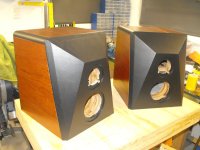
The rear panels of my subs were entirely routed using an ancient and cheap indexing table and the 25-year old 1/2" router in the background:
You have to want to do it for yourself anyway, by yourself. If you do, start from there and see what happens.It was informative and one of things I learnt was that people won't necessarily come.
Maybe we can make a google drive folder that stores findings? Sticky the folder to the beginning of the main thread?So is it time to bring the 3d stuff together in one place along with some open source tools so that people with an interest in the engineering details of their speaker designs can work together to push things forward?
I have just spent a day getting the old and I think now abandoned acousto BEM code to compile against current versions of libraries like MPI and ported it to run on Windows rather than just unix (still has a bug but runs). It needs refactoring to create a sane set of apis in order to support adding the features we would need. It should only take a day or two given it is an already working code. It would still lack some of the features in akabak but being open source and cross platform it is likely to be a better base for going forward with the BEM aspect of a group project.
Not sure this is the right place for the discussion. I posted something similar in a thread on on-wall speakers without sparking any interest.
I think it would also be helpful if we had a google drive folder with MDAT data collected from different drivers. It would make it easier for all of us to choose drivers when planning out a build.
I can set this up if people are interested.
I see a wealth of information stored in the brains of the people here, none of it archived properly.
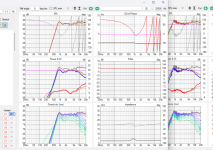
BTW I did take off axis of base and V1 edge. I sort of ran out of time. I also screwed something up and lost the raw MDAT of the off axis of V1.
So these two have slightly different smoothing and IR because I was running out of time but here's an off axis comparison. Might as well look exactly the same though.
So these two have slightly different smoothing and IR because I was running out of time but here's an off axis comparison. Might as well look exactly the same though.
Attachments
Andy19191, I think barrier would need to be very low for any wider BEM adoption. It should be as easy as VituixCAD diffraction tool, and even seems too intimidating for many 😀 What we need is stuff that runs on web browser so that no installation of anything is needed. Perhaps prepare an interactive scene of speaker box, where the user can tweak some of dimensions and stuff like that, and see what the resulting response is in real time. Perhaps teach an AI to do the graphs, or pre-calculate it all so that it runs realtime. Then offer the tool on the side for anyone to tweak their own system to it.
Maybe we can make a google drive folder that stores findings? Sticky the folder to the beginning of the main thread?
I think it would also be helpful if we had a google drive folder with MDAT data collected from different drivers. It would make it easier for all of us to choose drivers when planning out a build.
I can set this up if people are interested.
I see a wealth of information stored in the brains of the people here, none of it archived properly.
Thanks but I set up a github account a couple of years ago for a project that didn't happen. It should handle a group project smoothly. I will post my initial words and code there and then we can talk around it. Perhaps somewhere else will be better in the longer term but this is my initial intention to get things going.
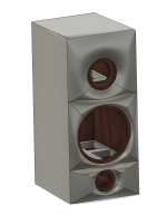
Looks like the Abbey except it’s ported. http://www.gedlee.com/Loudspeakers/Abbey.aspxIts not exactly perfect but maybe something more extreme like this will make a bigger difference. I can test this
This needs its own build thread, or is there one already?If one has a table saw with a tilting blade they can be simply (if slowly!) accomplished with a number of angled cuts and some block sanding; a near-perfect profile being finally achieved with a profiled sanding block The maximum radius is dependant the saw's depth of cut at 90 degrees. Any profile - circular/parabolic/Tractrix/oval - can be easily achieved in this manner. I have 125mm cut on my saw so I could do quite big ones, and with a little jigging, could probably do even larger on the bandsaw!
On the subject of jigging, a rotating speaker-holding fixture and a router running along a track would also work well for radius profiles. With some ingenuity it is possible to build some pretty exotic speakers with only a handsaw, a router, and a handful of bits.
The rear panels of my subs were entirely routed using an ancient and cheap indexing table and the 25-year old 1/2" router in the background:
View attachment 1356579
Let me know when you have it up. We all should be archiving the data we are collecting.Thanks but I set up a github account a couple of years ago for a project that didn't happen. It should handle a group project smoothly. I will post my initial words and code there and then we can talk around it. Perhaps somewhere else will be better in the longer term but this is my initial intention to get things going.
I will throw everything I have into it
Arthur,
I am sure they used a similar modeling tool and work flow as I did. Mine is more dramatic but I can modify that easily.
I am sure they used a similar modeling tool and work flow as I did. Mine is more dramatic but I can modify that easily.
Basically if no gate and smoothing value are stated, the measurement could be one of those ungated measurements that someone smoothed 1/3 octave that means hardly anything. With a 5ms gate (200hz resolution) tweeter measurements typically don't need smoothing, but YMMV. If you have some sort of elevated measurement platform or an anechoic chamber you could go longer than that, but....Yeaaahhhhh.... I already played around it but since you asked.... here ya go. 1/12th smoothing gated at 5ms
You can do a lot of this work with diffraction modeling tools like the old BDS. A fancy shape won't be much different from a radius. An ellipse will act like a larger radius at first and then like a smaller radius for the later diffraction sources. Not sure if VituixCad can do a radius curve for diffraction, but those old Harry Olson diffraction images all have the same problem, they are all in the exact geometric center of the shape and they are a small source. Once you go even slightly off center even the circle and the square don't look so bad.
I have a very big shop with high ceilings and I do my tests up high in the air. Let's me get away with much longer gating.
But yeah, form what I am seeing so far you need some pretty extreme shapes to make a difference.
But yeah, form what I am seeing so far you need some pretty extreme shapes to make a difference.
That will make a difference but it is not likely to be a positive one. Creases are not good and making something like a waveguide start at the edge of the tweeters faceplate is also a way to introduce negative diffraction effects.Its not exactly perfect but maybe something more extreme like this will make a bigger difference. I can test this
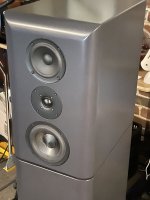
This image shows where the edge rounding starts and as close to the drivers as possible is a good idea.
For a non waveguided approach this is an option. The ridges and sharp corners are not ideal and their diffraction effects can still be seen, that can be avoided by rounding all the sides as is shown in the waveguide version above.
- Home
- Loudspeakers
- Multi-Way
- Edge Diffraction Testing - Shapes