I ran two PCM1794A in mono mode and had a lot of problems until I added 22R (IIRC) series termination resistors at the WM8805 I/O.
Ok. I'll include those in my design. So those 22R are right after the WM8805? (Nothing at the PCM1794A end? Not sure what they look like inside in the PCM1794A on those pins.)
I don't see such resistors on the WM8805 receiver I bought.
Last edited:
SPDIF is normally terminated in the receiver end with a 75-ohm resistor to ground. If you have two receivers only the one at the end of the line should be terminated.
Ok.
I was also thinking of putting each mono DAC with the amplifier next to the speaker. (Monoblocks.)
As a result I was wondering about buffering/splitting the SPDIF signal and running those separately to each monoblock with each mono mode PCM1794 DAC colocated with the monoblock amplifier. When I order the boards I get five of each so making pairs of WM8805, DAC and amplifier boards is fairly easy.
Any suggestions or advice on buffering and splitting the SPDIF signal?
This might be a terrible idea but I was thinking of testing the idea by running the coax SPDIF to the left WM8805 + DAC + Amp and the optical SPDIF to the right WM8805 + DAC + Amp. Is that a bad idea for a test? At least I eliminate any comments on the type and length of the interconnects and speaker cables🙂
Last edited:
You should probably have two SPDIF transmitters with transformer isolated outputs. Also, there are active TOSLINK splitters, but its probably more jittery that way.
Either that or you might try daisy-chaining the SPDIF receivers with only the one at the end of the line terminated. There would be some capacitive loading by unterminated receiver, don't know if it would cause any issues.
IMHO, probably best to put mono block amps at the speakers and run line level signals from a dac or preamp in the middle. You might want to use balanced if any problems with SE.
Last edited:
You could just build or buy a digital audio distribution amplifier. Works well enough in the pro world.
I am quite happy with the WM8805 (in master mode) driving the PCM1798/4 boards.
So far I have just used the WM8805 as a receiver. (And two in series for a loopback test, one receiver (master mode) and one transmitter (slave mode).)
I was wondering if that same single WM8805 chip can take the output of my PCM1802 ADC module (via DIN/WW8805 pin 17) and transmit the PCM1802 data output via TX0 (WM8805 pin 21) while that same single WM8805 chip is driving the PCM1794 via DOUT from RX0? I assume yes since it is a transceiver and was probably designed to do both at the same time?
I am doing everything in hardware mode.
I am just using the PCM1802 module for learning purposes. Later I plan on using a PCM1804 or newer differential ADC.
As a result I was wondering about buffering/splitting the SPDIF signal and running those separately to each monoblock
You can use logic gate as buffers. I'd use a 74AHC86 quad XOR gate, which works well on 3V3, with two gates per SPDIF output. The reason for XOR is to send one SPDIF stream with normal polarity, and the other stream inverted. This way the power supply current of this driver will be constant even if the uses parallel termination. The SPDIF receiver doesn't care about polarity, only about transitions, so it will decode correctly in any case.
Add a 120R resistor in series with the output of each gate. Combined with the output impedance of the gate, that makes about 150R, and two in parallel make 75R, so the cable is matched. Add an output AC coupling capacitor, 100nF SMD Film.
There is no need for a transformer on the transmit side. Why put two transformers in series? Also it prevents grounding the connector, so you get extra EMI.
The ground of the BNC or RCA connector should be tied to the ground plane RF-style (ie, 4 pins).
RCA sucks at HF but if you get the correct connector you can still get good signal integrity. It has to have proper grounding, like this or like this (90° angle). Isolated RCA connectors will result in more EMI. This type of double RCA connector has no proper grounding and will result in more EMI.
Get a proper coax and a RCA connector with a metal shell. Price is irrelevant, the cheap ones work just as well as long as the shell is metal and acts as shield.
You can also use optical, of course. It gives a bit more jitter, but WM8805 is good at cleanup. If you use two, use an inverted signal for one of the transmitters, so supply current is constant.
Not entirely sure, the PCM1794 mono mode is designed to be differential output, although you could combine them in phase instead for a single-ended output, which would be parallel.
If you don't use the differential output, then supply current will be variable. Does this DAC like a power supply with audio signal on it? I have no idea.
You mean the pictured (attached image) board is not recommended?
It has a split ground plane.
SPDIF is normally terminated in the receiver end with a 75-ohm resistor to ground. If you have two receivers only the one at the end of the line should be terminated.
You should never do that unless you want extra jitter.
If you want a transformer, use Murata DA102, then read the PDF and use the termination on page 8, with CT equal to the capacitor you put in series with the transmitter. That gave the best measurements, so I'm sharing 😀

What you should do is AC-terminate with a 75R resistor in series with the same capacitor value you put in the transmitter.
Attachments
Last edited:
Later I plan to design a better board or buy and use a better SPDIF to I2S receiver.
There's no better chip than the wolfson, it is very effective at removing jitter.
HOWEVER its output is only as clean as its own oscillator, and its internal xtal oscillator circuit is not good. If you use an external canned oscillator, you will get much lower jitter.
The above FFT, which is pretty clean, was done with a Vectron VCC1 which cost about $2 at the time, unfortunately now unobtainium.
> I was wondering if that same single WM8805 chip can take the output of my PCM1802 ADC module (via DIN/WW8805 pin 17) and transmit the PCM1802 data output via TX0 (WM8805 pin 21) while that same single WM8805 chip is driving the PCM1794 via DOUT from RX0?
Yes it can do that but you should pay attention to what clock mode you use. You can synchronize it to the incoming SPDIF clock, or you can let it be clock master, but in this case I'm not sure it can handle two different clocks at the same time (its own master clock and the incoming SPDIF clock).
Great. Thank you for all the help.
Right now one of my WM8805 is using an external canned oscillator. It is "RALTRON C019100 12.000-X". I don't know how good or bad it is.
My own design board is using the internal xtal oscillator circuit so I will get a canned oscillator for that one.
When used as a receiver in hardware mode and master mode is the jitter cleanup automatic with the WM8805? (I assume yes.)
If in hardware mode do you just route DOUT to DIN on the WM8805 if you want to use it to cleanup jitter and re-transmit?
> Right now one of my WM8805 is using an external canned oscillator. It is "RALTRON C019100 12.000-X". I don't know how good or bad it is.
No idea!
> When used as a receiver in hardware mode and master mode is the jitter cleanup automatic with the WM8805? (I assume yes.)
If it extracts the clock from incoming SPDIF it will automatically clean it.
> If in hardware mode do you just route DOUT to DIN on the WM8805 if you want to use it to cleanup jitter and re-transmit?
I think so, yeah.
You should never do that unless you want extra jitter.
Agree there will be a lumped capacitance somewhere in the middle of a transmission line (at the first SPFIF receiver) which will cause reflections. Basic TDR stuff. Its obviously not completely ideal.
Probably better to use two SPDIF transmitters and separate cables.
Dude, it has nothing to do with transmission lines...
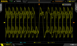
The transmitter is AC coupled, so if you put a parallel RC termination in the receiver, the signal will be high-pass filtered quite strongly, so the timing of the edges will move depending on what data was transmitted a few bits before, which increases data dependent jitter. Same if the signal is lowpassed (but worse).
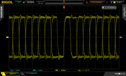
Lowest jitter comes when the waveform looks pretty at the receiver, with flat tops, straight edges, and square corners.
Also if you feed two receivers from one source using one cable with a tap in the middle, yeah you'll get lots reflections, but that's another can of worms... Same reason PCI, Ethernet, SCSI, AppleTalk, IDE/PATA, etc, all of them abandoned the bus topology and went point to point.
The transmitter is AC coupled, so if you put a parallel RC termination in the receiver, the signal will be high-pass filtered quite strongly, so the timing of the edges will move depending on what data was transmitted a few bits before, which increases data dependent jitter. Same if the signal is lowpassed (but worse).
Lowest jitter comes when the waveform looks pretty at the receiver, with flat tops, straight edges, and square corners.
Also if you feed two receivers from one source using one cable with a tap in the middle, yeah you'll get lots reflections, but that's another can of worms... Same reason PCI, Ethernet, SCSI, AppleTalk, IDE/PATA, etc, all of them abandoned the bus topology and went point to point.
Attachments
Last edited:
If you want a transformer, use Murata DA102, then read the PDF and use the termination on page 8, with CT equal to the capacitor you put in series with the transmitter. That gave the best measurements, so I'm sharing 😀
I will look at the Murata DA102. The ones I have are "PE-65612NL PE65612NL PE-65612 PULSE TRANSFORMERS FOR DIGITAL AUDIO".
Any idea if they are good or bad?
I have number of cables with real coax construction and they work well for coax SPDIF. The problem is that the RCA connectors are far too tight for repeated connection/disconnection in a lab/prototype setting. They are ok for install once and forget applications.
I was thinking of repurposing a Belkin component video cable. The connectors are not so tight and the coax construction looks like reasonable quality. Is there any reason not to use such a cable for SPDIF?
I don't want to break the coax SPDIF connectors on the E-MU 1616m. The whole connector and board is moving and twisting with the super tight connectors on the other cables.
Properly seating connectors help minimize jitter. If going through a FIFO somewhere, such as iancanada's, then incoming jitter should not matter unless it is severe enough to cause bit errors. OTOH, if you don't notice any audible difference between tight, gold plated (not fake Chinese gold color metal) connectors and good quality cable verses the cables that don't mechanically stress the sound card, then maybe no problem (or the dac isn't good enough yet to make the problem audible).
Last edited:
No experience with that one but I'd be concerned about the apparent lack of any high value caps on the opamp power rails and no PSU regs for them.
The layout looks to be designed to use the board as a teaching aid.
I have one of these, with most parts swapped for better ones. I got it to compare to my own (very)barebone dual PCM1794 boards.
Mine only has I2S in and the outputs are routed directly to the I-out pins.
I made it this way to be able to play around with everything before and after the DAC IC's.
I do have both electrolytic and film caps for decoupling the supply pins though.
To the ebay version, one could quite easily put at the least 100uF caps on the bottom of the board, soldering them to the pins of the film caps. Just a thought.You'd need a bit higher stand-offs though.
Personally, I prefer not having PSU regs on the board, saves me the trouble of removing them to use better ones.
Btw, how is that u-controller based OS-filter coming along?
The ones I have are "PE-65612NL PE65612NL PE-65612 PULSE TRANSFORMERS FOR DIGITAL AUDIO". Any idea if they are good or bad?
No idea, would have to look at bandwidth.
SPDIF is an excellent example of "what could possibly go wrong?"
Non competent receivers like CS8412 extract the clock from the whole waveform. Combined with bandpass filtering in the cable and transformer, that means the edges will cross the logic level transition point a little bit early or late depending on what the previous bits were (ie, jitter). That's why a wide bandwidth SPDIF transformer gives less jitter, while the low-end bandwidth extension is absolutely useless for actually decoding the bits correctly.
Note WM8805 is smart, it locks only on the preamble which is a constant sequence of bits, so it is not affected by the bits that came before, since they're always the same.
So what matters most with WM8805 is giving it a nice clean clock oscillator. Also, a low noise reg on PLLVCC would be nice. No need to go over the top, one of the nice little cheap regs like LP2985 ADP151 etc are great.
> The problem is that the RCA connectors are far too tight for repeated connection/disconnection in a lab/prototype setting.
Damn I've broken all the solder joints on the PCB of my previous amp with these annoyingly tight connectors. I ended up loosening up the jaws a little with pliers, but then they broke off lol. Quality!
The AV composite cables are usually crap, they're the same cables as cheapo audio RCA cables, ie not really 75R and the shield not braided so it is full of holes. If you've ever cut one of these to make a pigtail you'll see what I mean. If you can find thin flexible 75R coax that would be better...
Since then I get the neutrik RCAs, they're not expensive, and they're just the right diameter, you get good contact, and very easy to plug and unplug.
So what matters most with WM8805 is giving it a nice clean clock oscillator. Also, a low noise reg on PLLVCC would be nice. No need to go over the top, one of the nice little cheap regs like LP2985 ADP151 etc are great.
I used several independent "Denoiser" circuits with LM317 for my PCM1794/8 board. Do you think that is good enough for WM8805? I can start with that schematic and layout with the regulators already done. I had actually bought some very low noise MIC5205 and MIC5219 but they turned out to be fakes so I went with the LM317 + BC337-40 denoiser.
For my next boards I was thinking of upgrading the LM317 to the "Dienoiser" configuration. I know I am overdoing it but the input to the Denoiser regulators are 9V linear regulated wall wart supplies. I had them so I used them.
Since then I get the neutrik RCAs, they're not expensive, and they're just the right diameter, you get good contact, and very easy to plug and unplug.
Well I love the Neutrik XLR and 1/4" connectors. Those are my favorites. So I'll try their RCA connectors.
I just tried the DOUT to DIN loopback in hardware mode on my protoboard and that works (with of course setting the CSB/GPO2 pin 9 for the correct source). Next I can add buffers and test the ADC by routing the DOUT to the PCM1794/8 and DIN to the PCM1802.
I will look at the Murata DA102. The ones I have are "PE-65612NL PE65612NL PE-65612 PULSE TRANSFORMERS FOR DIGITAL AUDIO".
Any idea if they are good or bad?
I've tried Murata DA101C and PE-65612, but I'm really itching to try Lundahl LL1572 🙂
For now though, they are a bit expensive with other projects having to be the priority.
- Home
- Source & Line
- Digital Line Level
- Ebay parallel PCM1794 DAC any good