I used several independent "Denoiser" circuits with LM317 for my PCM1794/8 board. Do you think that is good enough for WM8805?
It should work fine.
Data dependent jitter sounds like distortion. When a digital chip processes the data bits its supply current will be somewhat correlated to the data. So using separate regulators for DVCC, PLL_VCC and the clock should work well. I used a lower noise version of TL431 (SPX2431), it's pretty cheap.
Upgrading the regulators to a denoiser might sound better, that's probably diminishing returns, but the denoiser is also pretty cheap and very high value for money, so, why not!
However if you use an offboard regulator for your digital power supplies, it would be nice to put a ferrite bead in there so the HF noise stays in the local loop between the chip and its ceramic decoupling cap. That will prevent the wires to the offboard regulator from acting as antennas and radiating the noise.
Basically, on the power pin: 10µF MLCC X7R 0805 // EEUFR0J471 or another alu cap with 2.5mm pin spacing (this is for ESL), I like FR because they have just the right ESR, inexpensive, long life, etc
Then ferrite BLM18EG601, I like Murata ferrites because they give the spice models, which is convenient
Then any low cost "general purpose" electrolytic > 100µF with high ESR // MLCC 100nF to 10µF, value uncritical
Then wire to your offboard regulator.
This makes a CLC filter. I'm giving you the part numbers because I tested this combination for absence of ringing between the ferrite bead (which is an inductor) and the caps, also absence of antiresonance peak between the electrolytics and the MLCCs. If you put a ferrite to tame HF noise between 2 MLCC often you get a huge LC resonance at 10-20 kHz because the damping factor is R/2 sqrt(C/L). So low µF low ESR caps like MLCCs give low damping. And a cheap general purpose high-ESR electrolytic cap gives perfect damping.
I've unscrewed the Neutrik RCA connector to have a look: I had forgotten what's inside, for 2€ you get a real metal shell (anodized black), rubber strain relief, and there's a plastic cable lock inside that get squeezed as you screw it so the solder joints don't break off...
Same reason I like DA102 transformer: it measures well, works well, and costs €1.33 on mouser.
Did you look at the wave forms with the PE-65612 with a scope? Or any jitter measurements?
Since I have the PE-65612 it would be nice to know how well they perform.
No, actually I haven't.
I couldn't tell you any subjective listening opinions either as most of the other equipment (amplifiers etc) changed as well.
I do have another digital isolation (pulse) transformer, it was listed in the BOM for the first DAC I built after having bought the bare PCB. That was the (in)famous Analog Metric dac. I don't remember what model or make that transformer was.
I have however liked the times I've heard Lundahl transformers used as DAC output among other things.
They aren't cheap though, but if everything else is "right" (very subjective) in the system, then I consider it a worthwhile investment.
So my PCM1794 chips arrived and look identical (molding, "Japan" on the bottom, leadframe, printing, font, logo, etc) as my PCM1798 test chip. I used ChipQuik Bismuth alloy to swap the chips and my homemade DAC is still alive. As expected the output current and I/V output voltage jumped as expected moving from PCM1798 to PCM1794.
With the PCM1798 the I/V op-amps were pretty warm. Now that I have the PCM1794 in there the OPA1612A are really hot as in hard to touch with your finger. From what I have read this is not really unexpected with the PCM1794. I wonder if I should try to find some sort of heatsink to glue on the OPA1612A or not worry about it? I was thinking of the 7x7mm heatsink used for the network chip in the Raspberry Pi 4 heatsink set with four different size heatsinks.
Or should I just not worry about it?
I bought one from Taobao,
dual PCM1794 in a small box,
I added some bypass capacitors,
added 4 high speed diodes,
added a copper wire to grounding,
It sounds great,
I can't tell the difference from my denon dac which use 4 pcm1704 .
this dac use opa1612,
I leave it on 24/7.
there is hardly any warmth.
dual PCM1794 in a small box,
I added some bypass capacitors,
added 4 high speed diodes,
added a copper wire to grounding,
It sounds great,
I can't tell the difference from my denon dac which use 4 pcm1704 .
this dac use opa1612,
I leave it on 24/7.
there is hardly any warmth.
.
With the PCM1798 the I/V op-amps were pretty warm. Now that I have the PCM1794 in there the OPA1612A are really hot as in hard to touch with your finger.?
There is probably RF getting into the opamps and heating them up. You might be able to see some of it on a scope at the opamp outputs, but maybe not. One version of ES9038Q2M dac I built had the same issue. For the next version I put the I/V and differential summing opamps maybe 5" from the dac chip, with a continuous ground plane running between the dac chip and opamps. I then loosely twisted the dac inverting and non-inverting outputs for each channel together using wire-wrap wire, and ran each pair in contact with ground plane down to the I/V opamps. No more opamp heating. Also, I was not the only builder to observe the same heating effect.
Probably the twisted pairs of wire had some differential capacitance between the conductors, and some capacitance from each conductor to ground. Also, there was some series inductance in part due to the wires not be tightly twisted together. I sort of thought of it as being a distributed filter, as opposed to a lumped one.
Something to keep in mind is that too much capacitance to ground at an I/V opamp input will cause frequency peaking and possible instability. Adding series resistance after some capacitance but before the I/V input will help with the frequency peaking issue, but increase distortion. So, best to keep any capacitance as minimal as possible while fixing the heating issue. Adjusting opamp feedback compensation may be helpful too.
Last edited:
The layout is a four layer board with the outputs routed as a matched differential pair. That differential pair is only about 1.5 inches long. There is a continuous ground plan between the dac chip and the opamps.
I will look around with my TinySA Spectrum Analyzer to see if I can detect anything. My "scope" is only 1MSPS but I will look and see if anything strange shows up.
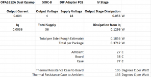
Since there is about -4V across the IV resistors at idle and the op-amp supplies are +/-18V the op amp has (18V-4V)*0.004mA*2 output stage dissipation just for the output current going into the I/V resistors. Then there is Iq of 3.6mA*2*36V.
So I very roughly estimate 259 mW = 14*0.004*2+3.6*2*36
Perhaps that is a lot for an SOIC-8? Especially soldered onto the tiny SOIC-8 to DIP-8 adapter boards? Maybe that is why so many PCM1794 boards use single NE5534 op-amps for the IV stage?
I found the following from Ti. I am concerned that the junction-to-ambient thermal resistance on the SOIC to DIP adapter boards is going to be a very high number.
I will look around with my TinySA Spectrum Analyzer to see if I can detect anything. My "scope" is only 1MSPS but I will look and see if anything strange shows up.
Since there is about -4V across the IV resistors at idle and the op-amp supplies are +/-18V the op amp has (18V-4V)*0.004mA*2 output stage dissipation just for the output current going into the I/V resistors. Then there is Iq of 3.6mA*2*36V.
So I very roughly estimate 259 mW = 14*0.004*2+3.6*2*36
Perhaps that is a lot for an SOIC-8? Especially soldered onto the tiny SOIC-8 to DIP-8 adapter boards? Maybe that is why so many PCM1794 boards use single NE5534 op-amps for the IV stage?
I found the following from Ti. I am concerned that the junction-to-ambient thermal resistance on the SOIC to DIP adapter boards is going to be a very high number.
Alexander Davis over 3 years ago TI__Expert
Hi Donald,
While we don't have the specifications listed for the OPA1612, the OPA2211 datasheet specifies the following:
RθJA Junction-to-ambient thermal resistance, high-K board 125 °C/W
RθJB Junction-to-board thermal resistance 28.8 °C/W
RθJC(bot) Junction-to-case (bottom) thermal resistance 19.1 °C/W
Last edited:
With my scope I see no sign of RF problems at the IV op-amps. Sniffing around with the TinySA Spectrum analyzer I see the master clock (and harmonics to hundreds of MHz) at -50 to -60 dBm everywhere near the WM8805 board and PCM1794 board but I do not see obvious problems with the IV op-amp.
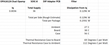
I used my IR thermometer to measure the OPA1612A IV op-amp, then the OPA1612A filter op-amp and then LM4562NA (PDIP) as the IV op-amp.
I have attached the rough estimates for the dissipation and the calculated thermal resistance. I am getting around 105°C per Watt Thermal Resistance Case to Board and 135°C per Watt Thermal Resistance Case to Ambient for the OPA1612A filter op-amp SOIC on the SOIC to DIP adapter board. For the PDIP package LM4562NA I am getting around 44°C per Watt Thermal Resistance Case to Board and 68°C per Watt Thermal Resistance Case to Ambient.
The IV Stage OPA1612A SOIC is measuring 77°C which is unpleasant to touch while the LM4562NA PDIP in the IV Stage measures 59°C which is much less unpleasant to touch.
So maybe it is just the thermal resistance of the SOIC and the SOIC to DIP adapter PCB given that this is a dual op-amp with fairly high output current with 36V total supply (+/-18V)? I guess 77°C feels pretty hot to the touch but perhaps is not a real concern.
Attachments

Last edited:
Haven't had thermal problems with single SMD opamps on dip adapters. OTOH, using dual single opamps to a single dip adapter, where the opamps are mounted on the top and bottom of the adapter PCB can get pretty warm. Side-by-side dual to single adapters seem okay though.
A diagnosis of RF heating might have to be made experimentally if insufficient test equipment to measure.
A diagnosis of RF heating might have to be made experimentally if insufficient test equipment to measure.
Last edited:
You could measure the actual supply current drawn by the opamps, that would answer the question. If the current is suspiciously higher than it should be, then it is... suspicious...
Has anyone used one of these DACs (they were on Aliexpress, not sure if they still are now)?
The description reads:
The description reads:
Product design:
This product adopts the FET discrete IV-LPF design 1794 analog circuit, which reduces the various disadvantages of using op amp design. The sound of the FET transistor design is more transparent, loose and natural, and more dynamic.
In addition:
The design of 1794 is designed as a mono mode of MONO, and a piece of 1794 is responsible for the output of one channel, which makes the 1794 show more unique and excellent sound. This is a better work than ever.
Attachments
You could measure the actual supply current drawn by the opamps, that would answer the question. If the current is suspiciously higher than it should be, then it is... suspicious...
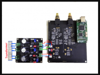
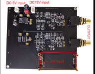
I added 1 Ohm sense resistors between the op-amp power regulator board and the DAC board.
With OPA1612A for the filter and LM4562NA for the I/V:
Clocks Off: 92.4 mA for -18V and 47.1 mA for +18V
Clocks On, Idle: 92.5 mA for -18V and 47.0 mA for +18V
Clocks On, Playing: 92.6 mA for -18V and 46.9 mA for +18V
With OPA1612A for the filter and I/V:
Clocks Off: 91.6 mA for -18V and 47.2 mA for +18V
Clocks On, Idle: 92.8 mA for -18V and 47.9 mA for +18V
Clocks Off: 93.4 mA for -18V and 49.2 mA for +18V (it is heating up)
Clocks On, Playing: 93.7 mA for -18V and 48.5 mA for +18V
Thus I am concluding this is simply heating due to the high output current and low value resistors in this PCM1794 balanced circuit. The SOIC package is not helping plus they are dual op-amps and further they are on the tiny SOIC to DIP package adapter PCB.
As far as I can tell there is no issue with RF in the op-amps.
Last edited:
Might be worth a try lowering the opamp rail voltages. Usually, higher voltage tends to sound better, but not true for AK4499 combined with OPA1612. +-11v is where Topping set the opamp rails for D90. Since my regulators are adjustable, I checked from about +-9v to +-17v. Ended up finding the sweet spot at the same place Topping did, +-11v.
Good idea. Later I will sweep the supply voltage while checking measurements with the notch filter. I assume with the PCM1794 I will not be able to make meaningful measurements without the notch filter. The PCM1798 was already looking pretty good.
I searched for PCM1794 within this shenlongsi users listings, there's another dual PCM1794 which is fully assembled and ready to go, with LT1963's, OPA1612's for the I/V conversion, & a rollable muses 8820 so when you get tired of the sound you can upgrade the muses 8820.
They [possibly rightly] state that PCM1794 exceeds the ' details ' of CS4398, AK4493 & Sabre ESS ES9028, although aside from the hybrid architecture design in the PCM179x, it's still pretty difficult to show [or allege] scientifically how / where the PCM1794 can be superior. I'm pretty sure the ES9028 in current output mode is an approximate equal rival, anyway.
- SNY-30A CSR8675 PCM1794 Bluetooth 5.0 receiver decoder DAC LDAC | eBay " SNY-30A CSR8675 PCM1794 Bluetooth 5.0 receiver decoder DAC LDAC "
The fully assembled ones are almost certainly populated with fake opamps and caps, so best avoided IMHO.
On the Chinese dual PCM1794 boards, the opamps are marked as NE5532 and NE5534, almost certainly low quality fakes.
But what to replace them with? I have seen one example where the NE5532 were replaced by OPA2602 and the NE5534 by OPA1611.
What other opamps have people tried?
But what to replace them with? I have seen one example where the NE5532 were replaced by OPA2602 and the NE5534 by OPA1611.
What other opamps have people tried?
Attachments
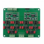
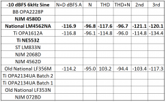
Well on my own PCB using only dual op-amps (and the PCM1798 before I swapped with the PCM1794) the attached show my measurements for a variety of op-amps.
For cost to performance ratio the LM4562 is really pretty good. I am using OPA1612A right now for IV and filter. But that is my own PCB design.
For singles I suggest considering OPA228 family and OPA1611A.
For cost to performance ratio the LM4562 is really pretty good. I am using OPA1612A right now for IV and filter. But that is my own PCB design.
For singles I suggest considering OPA228 family and OPA1611A.
Attachments

On the Chinese dual PCM1794 boards, the opamps are marked as NE5532 and NE5534, almost certainly low quality fakes.
Just FYI. I have received a number of fake NE5532 so yes, do be careful. For example the terrible CIRMECH CS4398 DAC came with a fake NE5532. Unfortunately the rest of the design/layout was so bad that genuine op-amps did not help it much.
- Home
- Source & Line
- Digital Line Level
- Ebay parallel PCM1794 DAC any good