I don't have spares but I replaced one of the NE5532's with a JRC4560 (equivalent) and measured the same current draw so I think the NE5532's are ok. I don't have lines connected to the PCM1794 at the moment but assume they have pulldowns or noise would translate to no output.
-12v is only pulling 23mA!
-12v is only pulling 23mA!
I'd not recommend these boards. The analog portion is not well layed out and opamps are oscillating(?) running extremely hot. Tested with various low-high grade opamp derivatives. You might use the board with passive I/V the like as DDDAC1794 but I've not gone this route.
Thank you I didn't read this. Yes it is a big problem, on the 12v line.
I've put a scope on one of the NE5532's, I'm seeing 0v at both inputs (as expected) but -4.16v at the output. This repeats with about +/- 0.1v across all 4 chips.
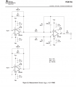
I don't get why the NE5532's are there anyway, the Ti document seems to suggest they're unnecessary (circuit attached for one channel).
I don't get why the NE5532's are there anyway, the Ti document seems to suggest they're unnecessary (circuit attached for one channel).
Attachments
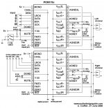
There isn't a specific schematic for mono mode?
I did some inspection, the NE5532 chip is doing the same as 2x NE5534 chips in the datasheet. It's using identical values (2.2n, 750ohm).
Probably best if someone can explain what all these op-amps are doing. My understanding is 1st is a I/V (with filter), second is a filter (high pass?) and final is...?
If -4v is normal then the heating has to be due to the current draw through the output resistor (680 ohm)? I don't see any noise on either power rails.
Not the one in question though. I don't understand the need for all the filtering but that's another question.
I think I understand where the -4v is coming from, the PCM1794A will be giving out half it's output (the current equivalent of voltage offset) at rest. That means the first op-amp is an inverted output IV converter with filter.
Two stages after that I don't understand.
Still no idea on the heat. The first stage outputs into a 680 ohm resistor. I see a 2.75v differential across this, equals 4mA current draw.
pos/inv * 4mA * 4 chips = 32mA (and I have 210mA). Doesn't seem like the output...
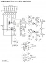
The number of op-amps is because it is mono mode. It results in better performance. Take a look at figure 26 (mono mode, page 22) in the Ti datasheet for PCM1794. Then look at the sub-circuits (figure 25, repeated) and then the explanation for the sub-circuits on page 19.
The mono mode basically doubles the circuitry the way Ti did it.
Your currents look too high. Something seems to be wrong.
The mono mode basically doubles the circuitry the way Ti did it.
Your currents look too high. Something seems to be wrong.
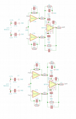
Getting somewhere. The last op-amp is a differential for the single ended output just as in the engineering datasheet. Using balanced output can save a few mA's and remove this op-amp.
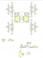
I reversed the components into kicad. Being cheap Chinese they've used the wrong capacitor values and adjusted a few resistors to save a few cents, and used the 5532 instead of 2x 5534.
I still don't know about the 5532's high current draw. The datasheet suggests a 820 for RF2 and 750 is installed. I'll try changing that.
Attachments
Thanks. I've come to the conclusion there's too many compromises. The 5V stage is noisy, the capacitors are wrong values, the 5532 saves $2 on parts and so on. Plus it uses 3W continuously which isn't great.
What it needs is a bit of a rethink, so I've done just that. A CPU watches the zero pin and after a settable period mutes the chips and shuts down the 12v and 5v supply.
Built in 12v/-12v supply from USB. Will require 0.5A from USB I reckon (currently at 0.65A but with lesser efficiency boost).
5V chips have 1/5 the noise of the 1117. 5534's used. 2% Panasonic film caps.
Last aspect to consider is the USB to I2S chip. Looking for asynchronous with built in clock generators and it would be nice to keep it Texas Instruments as with the rest of the chips. Any suggestions welcome!
Attachments
I based my own design on the Ti datasheet but I used all dual op-amps.
I have swapped between Ti 5532, OPA2228, OPA1612A and LM4562NA without any issues. (And many other duals that I had on-hand to try.) I have noticed that the SOP/SOIC-8 get pretty warm but I might not need the full +/-18V I am using. Later I will experiment with lower voltages.
I wonder which is best but it is hard for me to tell. OPA1612A has very low noise and distortion. But OPA2228 has much higher gain (160 dB!). The LM4562NA is between the two for gain.
Right now my next step might be to upgrade the op-amps in my ADC in an attempt to be able to make better measurements. The PCM1794 with OPA2228, LM4562NA or OPA1612A all sound very good to me. I also have difficulty measuring differences aside from small noise floor differences. The distortion spectra are all very similar. I suspect the layout, power supplies, components, signal source and signal integrity might be harder to get right and more important than is choosing between OPA2228, LM4562NA and OPA1612A.
Last edited:
It depends what you're output voltage is. Balanced is +/- 9v and TI5532 have a maximum 3v range, hence 12v is generally fine. No point going beyond this. If you're using 2v or 4.5v phono can go much lower.
I still haven't found a USB2I2S Async chip which doesn't require extensive programming (xmos, cmedia). It appears an out the box solution doesn't exist other than purchasing a one from aliexpress and ensuring I make the PCB so it plugs in.
I still haven't found a USB2I2S Async chip which doesn't require extensive programming (xmos, cmedia). It appears an out the box solution doesn't exist other than purchasing a one from aliexpress and ensuring I make the PCB so it plugs in.
WM8805 was strongly recommended to me on diyaudio and I am quite happy with the results. It is also quite economical.
I was warned to feed it a good (active) clock and not use the on-chip oscillator with a passive crystal. It is also suggested to use good low noise supplies including one for the PLL and one for the external active clock oscillator.
If I do another board I would like to put the WM8805 and the DAC on the same board so that I can avoid using Dupont wires/ribbons for the signals. I want nice clean fast edges and flat tops. No point in putting lots of effort and investment into low jitter if it is going to be ruined.
Last edited:
- Home
- Source & Line
- Digital Line Level
- Ebay parallel PCM1794 DAC any good