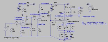
The 0.22nf Cap is only in the simulation.
22nF K40Y between the first and second stage.
32mW - 0.39% thd
64mW - 0.44% thd
128mw - 0.59%thd
0.25W - 0.78%thd
0.5W - 1.12%thd
1W - 1.65%thd
2W - 2.65%thd
3W - 3.45%thd
4W - 4.5%thd
5W - 6.1%thd
5.12W - 6.6%thd
7W - 10%thd
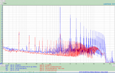
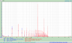
the inflection point is about 5.12W out, about 6.4Vrms into 8 ohms. the first plot is 6.4Vrms with nice monotonically decreasing harmonics, the second is 6.6Vrms with the high order harmonics produced by the onset of clipping.
This is also accompanied by a rapid increase in IM distortion.
64mW - 0.44% thd
128mw - 0.59%thd
0.25W - 0.78%thd
0.5W - 1.12%thd
1W - 1.65%thd
2W - 2.65%thd
3W - 3.45%thd
4W - 4.5%thd
5W - 6.1%thd
5.12W - 6.6%thd
7W - 10%thd
the inflection point is about 5.12W out, about 6.4Vrms into 8 ohms. the first plot is 6.4Vrms with nice monotonically decreasing harmonics, the second is 6.6Vrms with the high order harmonics produced by the onset of clipping.
This is also accompanied by a rapid increase in IM distortion.
Attachments

The K40Y 0.022uf in combination with the 470K grid resistor for the next stage has approximately a 15Hz -3dB point. No need to increase it as in promotes LF from a record player to be passed.
Stephe, I put a 100pF cap from grid to ground with the tube missing so the drive is sufficient. Any loss of ability to drive the 300B should show up as HF roll off where the the miller capacitance would be loading down the drive signal if there were an issue. From the frequency plots it is evident this is not an issue.
My THD numbers are actually THD+N, not just THD.
I was looking around for a reference and found Ales "300B SE Amplifier" test where he reported 1.426% THD+N at 1W. I saw 1.65% THD+N, so worse but greatly so.
I have taken the amp back upstairs to do listening tests so it will be a while before I get back to measurements.
I want to compare the Psvane (which I have been testing with) with the EH 300B Gold to see if I can hear any difference. The EH show slightly lower distortion.
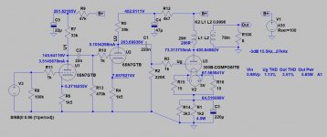
Due to the OPT high DCR (286R) the 60mA operating point current is one of the worst scenario.
Try to higher current (70mA or grater if the OPT is tolerate it) and distortion will be decreasing significantly.
The A1 border will not changing considerably, below 6W.
Over it the distortion growing rapidly (too high output impedance of driver + blocking distortion due to coupling capacitor).
Try to higher current (70mA or grater if the OPT is tolerate it) and distortion will be decreasing significantly.
The A1 border will not changing considerably, below 6W.
Over it the distortion growing rapidly (too high output impedance of driver + blocking distortion due to coupling capacitor).
Attachments
Last edited:
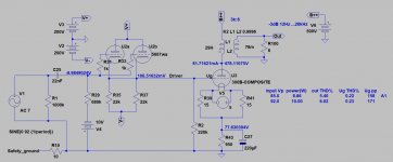
Transformer is rated at 110ma. I will try again. However I tried an additional 2.4K parallel resistor and Ia went to 73mA reducing the Vgk 64.3before clipping. I think increasing Vak is more promising.
Everything is relative.
The 8W number was one I arbitrarily pulled off the WE data sheet as a goal for the project. Many amp comparisons show power out at 10%thd, so that is a benchmark.
I do not need 8W, I only use the first watt, and that rather seldome.
I am not about to rush out and buy another pair of OPTs, so there is little utility to simulations of lower DCR in one. But thank you for your input as it confirms DC loss and distortion expectations.
In real world listening tests I have found I need 3Vp-p into 8 ohm speakers to achieve listening levels which I am comfortable with.
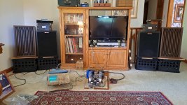
This corresponds to only 140mW. Both my Klipsch Heresy (1983) and Kenwood KL-5050 speakers (1974) are rated at 96dB/W-M. Side by side comparisons show I achieve the same measurable mid band levels with both at this level according to my el-cheapo RS SPL meter.
The Heresy speakers have a bit better/lower bass, and cleaner highs from listening tests (IMHO).
The 300B am is cleaner than my 6P41S amp (on top of the console). Bass is quite good considering the 50Hz roll off of the speakers.
The 8W number was one I arbitrarily pulled off the WE data sheet as a goal for the project. Many amp comparisons show power out at 10%thd, so that is a benchmark.
I do not need 8W, I only use the first watt, and that rather seldome.
I am not about to rush out and buy another pair of OPTs, so there is little utility to simulations of lower DCR in one. But thank you for your input as it confirms DC loss and distortion expectations.
In real world listening tests I have found I need 3Vp-p into 8 ohm speakers to achieve listening levels which I am comfortable with.
This corresponds to only 140mW. Both my Klipsch Heresy (1983) and Kenwood KL-5050 speakers (1974) are rated at 96dB/W-M. Side by side comparisons show I achieve the same measurable mid band levels with both at this level according to my el-cheapo RS SPL meter.
The Heresy speakers have a bit better/lower bass, and cleaner highs from listening tests (IMHO).
The 300B am is cleaner than my 6P41S amp (on top of the console). Bass is quite good considering the 50Hz roll off of the speakers.
Attachments
Last edited:
IMHO One Electron UBT-3 is not perfectly optimal for 300B, despite of aproximately suggest it in the datasheet.
http://www.one-electron.com/Products/Trans/UBT3_10.pdf
Tube Plate voltage current Grid bias Power
300B 325 V 75 mA -65V 7.5 W
If you use it with lower power, the higher impedance OPT (for example 5k) produces much lower distortion.
http://www.one-electron.com/Products/Trans/UBT3_10.pdf
Tube Plate voltage current Grid bias Power
300B 325 V 75 mA -65V 7.5 W
If you use it with lower power, the higher impedance OPT (for example 5k) produces much lower distortion.
Possibly hooking the speakers to the 4 ohm tap would help reduce the distortion, especially if the speakers are more like 6 ohms in reality.
Klipsch specs the Heresy at 10 0hm minimum.
Here is distortion at moderate listening level. I cranked it up to a level I use when I am in the kitchen cooking.
Here is distortion at moderate listening level. I cranked it up to a level I use when I am in the kitchen cooking.
Attachments
Last edited:
Since I am not sure what you consider "High" distortion I propose you provide me with examples of what your amps produce.
Adjust the volume of your system to produce a moderately high level of sound (69dB at 12' from the speaker) such that it can be heard in another room over the sound of cooking a meal with the vent fan running on the stove vent. Measure the p-p or RMS level and then use that as a reference level to measure the harmonic distribution spectrum of your amp at that level. Then post the screen shot so I can get a feel for the relative distortion of my amp.
This way I can have a relative measure of what I am working towards.
Thanks,
Steven
A reasonable view on an acceptable level. Distortion Misunderstood | Cascade Tubes
Seems to align generally with my experience of owning various low distortion transistor amps at one point compared with the 300b I have now. I don’t know the level of distortion but assume it is around 5-6%.
Seems to align generally with my experience of owning various low distortion transistor amps at one point compared with the 300b I have now. I don’t know the level of distortion but assume it is around 5-6%.
A reasonable view on an acceptable level. Distortion Misunderstood | Cascade Tubes
I agree and 2-3% of "good" distortion isn't a concern. 10% of any sort of distortion isn't even musical, at that point it has become a distraction because most likely the amp has been driven into clipping.
Maybe yes, maybe no, if other things change it could be.
Then again there is always the possibility that they transposed the numbers when entering the data.
Then again there is always the possibility that they transposed the numbers when entering the data.
Attachments
Last edited:
22nF K40Y between the first and second stage.
I was going to change the capacitor to a 0.15uF, until I realized that LF Fr is dominated by OPT and driver stage. Improving the LF coupling of the first to second stage will do little for real wold response.
How much audio content is there below the 15Hz -3dB point? Other than edge warp from vinyl records.
Last edited:
Hi, I'm interested in building this kit
I don't have the knowledge of all of you guys but I like to learn new things
I wonder if you can help me choosing the correct parts to building it
I already locate the board
300B Single ended Class A Stereo Amplifier Tube Amplifier Board Preamplifier PCB DIY Kit|Amplifier| - AliExpress
For the power transformer
AS-3T325 - 300VA 325V Tube Transformer - AnTek Products Corp
for the choke
LK-8H100 Toroidal Power Choke - AnTek Products Corp
For output transformers
MS-30W25 30W Single Ended Output Transformer - AnTek Products Corp
what do you think?
My kit arrived today and it is the black board v1.1, now I have to check the components
- Home
- Amplifiers
- Tubes / Valves
- eBay 300B PC board kit